
Bladeless fan

a bladeless fan and fan body technology, applied in the field of bladeless fans, can solve the problems of children's fingers being injured, user discomfort, and huge inconvenience to users

Inactive Publication Date: 2013-06-06
DONGGUAN XUERMEI ELECTRICALTECH
View PDF0 Cites 54 Cited by
  • Summary
  • Abstract
  • Description
  • Claims
  • Application Information

AI Technical Summary

Benefits of technology

The patent describes a new type of fan that doesn't have blades. It has a rotating part that generates airflow and a fixed part that drives the rotating part. The fixed part has a screen to control the fan and an air suction hole. The fan is powered by a motor that drives a turbine. Overall, this fan is designed to be more efficient and safe than traditional fans.

Problems solved by technology

As the protective cover of the fan has a plurality of openings, it is possible that children's fingers may be injured.
In addition, since the general fan creates airflow using blades, a strong air flow is generated with inconsistent intensity so that the user may feel uncomfortable.
The blades have to be detached, re-assembled and tested for cleaning, and the whole process causes huge inconvenience to the user.
The above fan does not need outwardly-exposed blades and its function is only to push airflow to circulate so that it fails to meet the recent demand for a multifunctional device and leads to a less noticeable practicality.
Hence, it is inconvenient to manipulate the level of airflow intensity and to turn on / off the fan.

Method used


Image

  • Bladeless fan
  • Bladeless fan
  • Bladeless fan

Examples


example 1

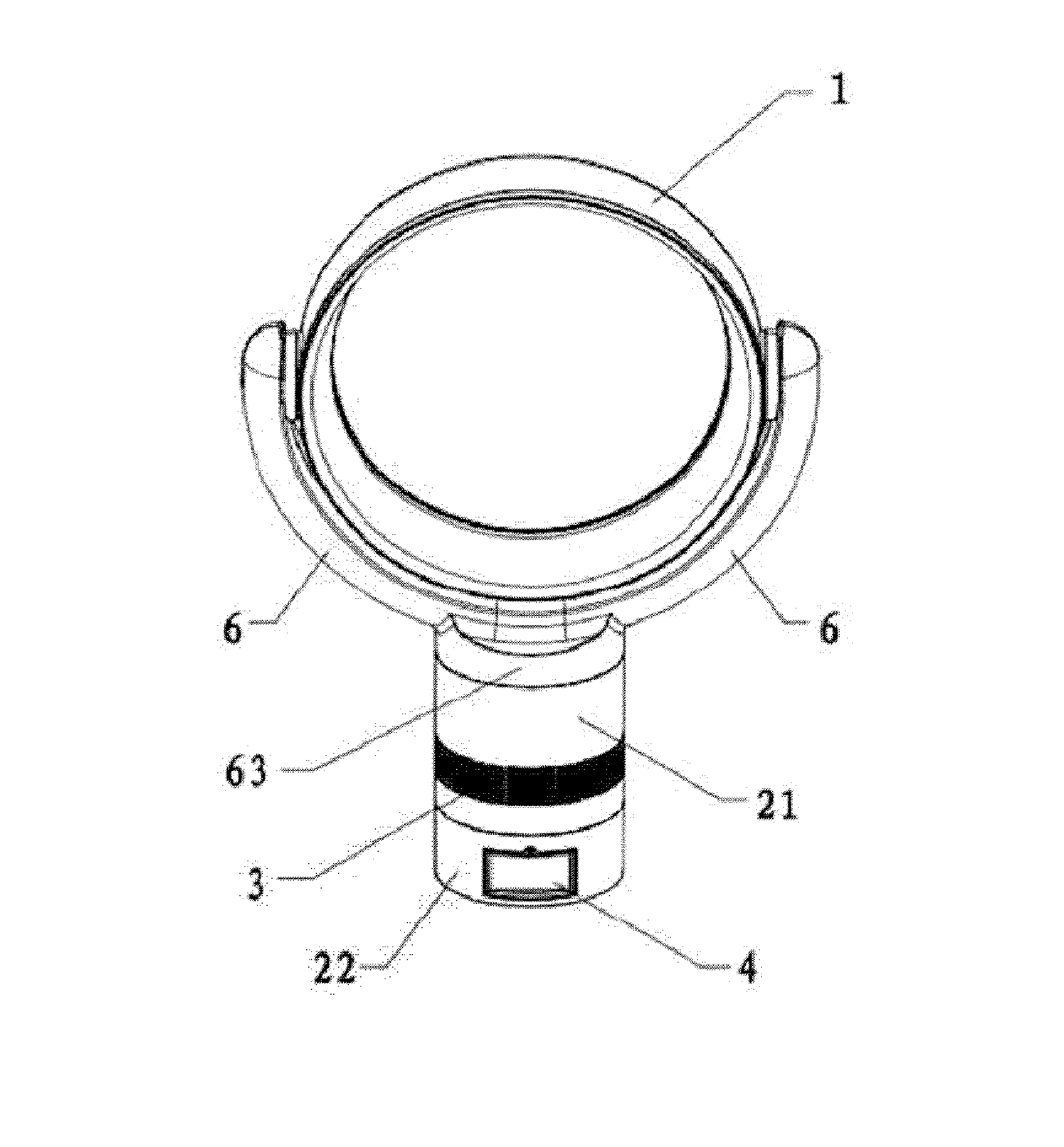
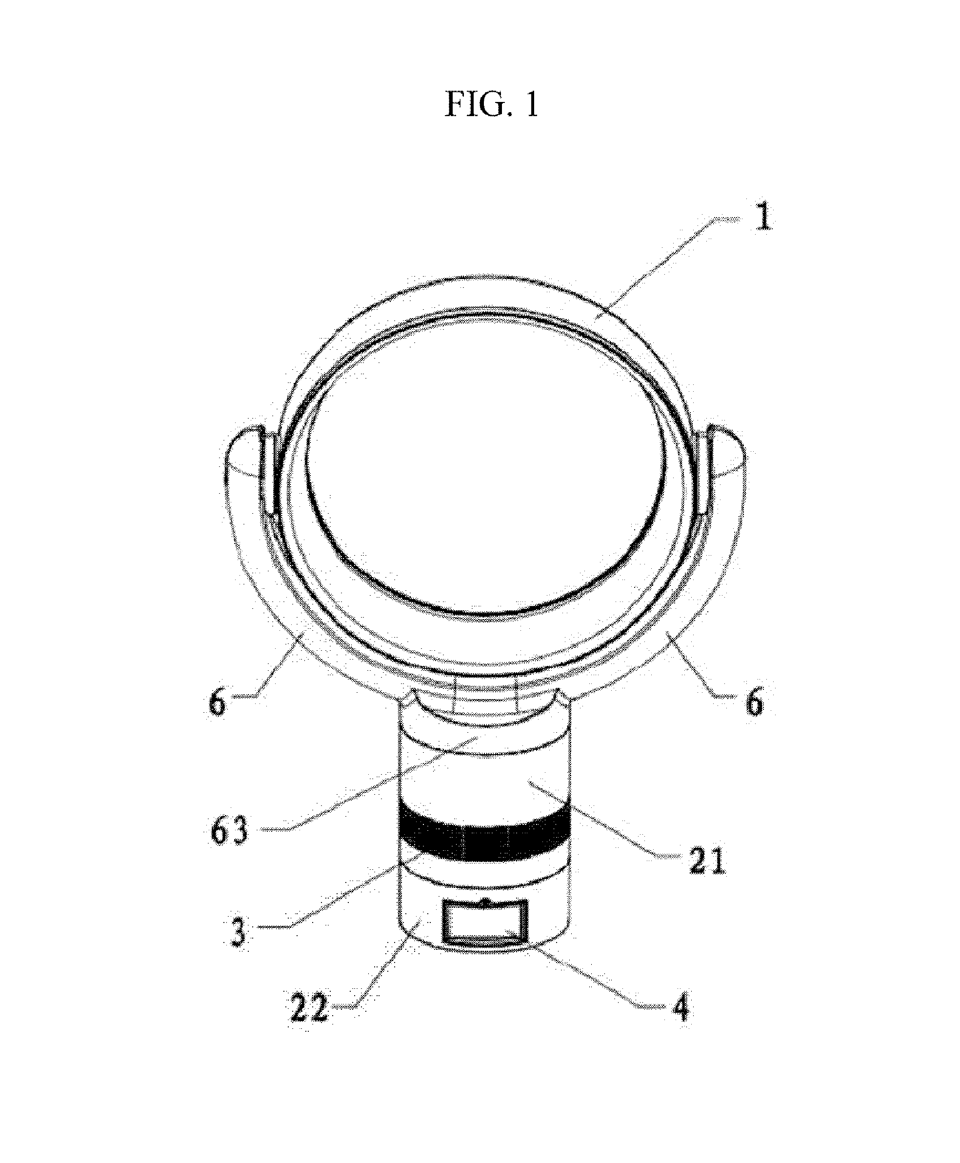
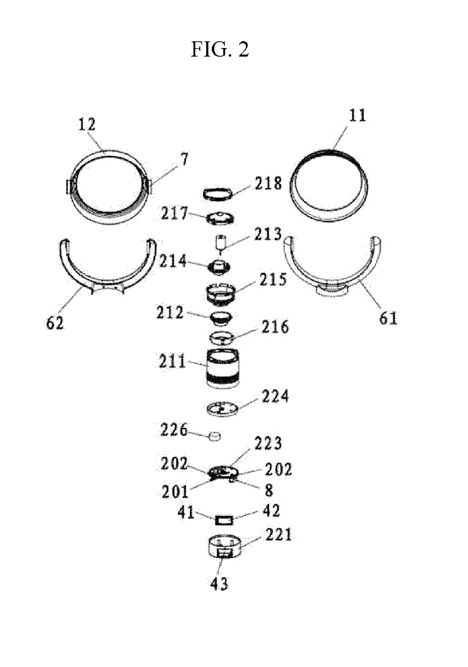
[0047]As shown in FIGS. 1 to 5, a bladeless fan according to an exemplary embodiment of the present invention includes a base 2 configured to generate airflow and an blower 1 configured to include a blowhole on the front-end to blow the airflow, the base 2 includes a rotating body 21 configured to generate the airflow and a fixed body 22 installed below the rotating body 21 and drive the rotating body 21 to horizontally rotate, the rotating body 21 includes a rotation case 211 connected to the blower 1 configured to include a turbine 212 and a motor 213 which are installed inside of the rotation case 211, a rotation of the turbine 212 is driven by the motor 213, an air suction hole 3 is formed on the sidewall of the rotation case 211, the fixed body 22 includes the fixation case 221 and a synchronous driving mechanism 222 fixed on the top of the fixation case 221 and configured to drive the rotation case 211 to horizontally rotate, and a touch screen controlling device 4 is installe...

example 2

[0058]As shown in FIGS. 6 to 10, the present example is different from the first example in that an atomizing device 5 is installed below the fixed body 22 and that the atomizing device 5 and the fixed body 22 are detachably connected to each other and that the atomizing device 5 includes a water tank body, a ultrasonic atomizer 52 connected to a water tank body, an air-blowing mechanism 53, an atomizing mechanism installed above the ultrasonic atomizer 52 and the second PCB 55 connected to the ultrasonic atomizer 52 while the atomizing mechanism is installed in the back-end of the blower 1 and the second PCB 55 and the touch screen controlling device 4 are electrically connected to each other.

[0059]Resonance is generated through a vibration circuit and a unique vibration frequency of a piezoelectric ceramic so that the size of the liquid droplet atomized by the ultrasonic atomizer 54 which is in direct contact with the piezoelectric ceramic is between 1 μm and 3 μm. The liquid drop...

example 3

[0069]As shown in FIGS. 1 to 3, the present example is different from the second example in that an air suction hole bracket 6 is installed between the rotating body 21 and the blower 1, that the blower 1 and the air suction hole bracket 6 are hinge-connected, that suction units 63 are formed below the air suction hole bracket 6, that the suction units 63 are detachably installed on the rotation case 211, that the suction units 63 have a larger cross sectional area than the bracket 218 and that the blower 1, the air suction hole bracket 6 and the rotating body 21 form an airflow passage.

[0070]The suction units 63 are detachably installed on the rotation case 211, the caliber of the suction units 63 have the same size as that of the rotation case 211 so as to ensure that, if airflow is generated in the rotating body 21, the airflow smoothly goes through the suction unit 63 into the air suction hole bracket 6, and the suction units 63 are installed on the left side and the right side ...


PUM


Abstract

Provided herein is a bladeless fan including a base and an blower. The base includes a rotating body configured to create the airflow and a fixed body installed below the rotating body and configured to drive the rotating body to horizontally rotate, the rotating body includes a rotation case being connected to the blower and having installed therein a turbine and a motor, the motor drives the turbine to rotate, an air suction hole is formed on the sidewall of the rotation case, the fixed body includes a fixation case and a synchronous driving mechanism configured to be fixed on the top of the fixation case and drive the rotation case to horizontally rotate, and a touch screen controlling device is installed in the fixation case.

Description

CROSS-REFERENCE TO RELATED APPLICATION(S)[0001]This application is a National Stage of International Application No. PCT / CN2011 / 081661 filed Nov. 2, 2011, claiming priority based on Chinese Patent Application No. 201110291841.9 filed Sep. 30, 2011, the contents of all of which are incorporated herein by reference in their entirety.FIELD[0002]The following description relates to a fan, and more particularly, to a bladeless fan.DESCRIPTION OF RELATED ART[0003]A general fan is composed of a fan frame, a driving motor installed in the fan frame and rotatable blades connected the driving motor. Generally, a blowhole in front of the blades is covered by a protective cover for safety. As the protective cover of the fan has a plurality of openings, it is possible that children's fingers may be injured. In addition, since the general fan creates airflow using blades, a strong air flow is generated with inconsistent intensity so that the user may feel uncomfortable. The blades have to be deta...

Claims


Application Information

Patent Timeline
IPC IPC(8): F04D29/00
CPCF04D29/002F04D25/10F04D29/705F04F5/16F04D25/08F04D29/40
Inventor ZOU, XIAOMIN
Owner DONGGUAN XUERMEI ELECTRICALTECH
Learn More