Photovoltaic cell assembly

Active Publication Date: 2013-06-20
DOW GLOBAL TECH LLC
View PDF4 Cites 85 Cited by
  • Summary
  • Abstract
  • Description
  • Claims
  • Application Information

AI Technical Summary

Benefits of technology

[0008]It is believed that one potential benefit of the present invention over the prior art is that the inventive photovoltaic cell assembly is constructed and configured in such a way that the horizontal planes of the solar cells need not be substantially coplanar in order to maintain electrical connection between the photovoltaic cells. This provides additional degrees of freedom with respect to the flexibility of the module, in addition to the flexibility provided by the flexible solar cells. The additional flexibility is provided by a conductive interconnect element that is folded (or bent) at least once, preferably about the longitudinal axis (i.e. axis parallel to longest dimension). It is contemplated that the fold (or folds) may be located not in the center of the conductive interconnect element and/or along its longitudinal axis, just so long as it is folded at least on

Problems solved by technology

It is believed that the cross section of the wire may be limited such that thicker wires are too stiff and thin and wide wires obscure too much light.
This process may be difficult to use with thin film solar cells because the resulting series string of cells may be fragile and susceptible to lo

Method used


Image

  • Photovoltaic cell assembly
  • Photovoltaic cell assembly
  • Photovoltaic cell assembly

Examples


Example

[0024]The present invention relates to an improved photovoltaic cell assembly 10, as illustrated in FIGS. 5, and can be described generally as an assembly of a number of components and component assemblies that functions to provide electrical energy when subjected to solar radiation (e.g. sunlight). In one example, the improved photovoltaic cell assembly 10 may be incorporated into a larger photovoltaic device, for example a solar shingle 100 as shown in FIG. 6.

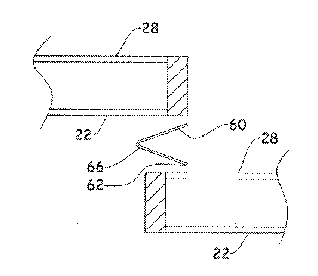
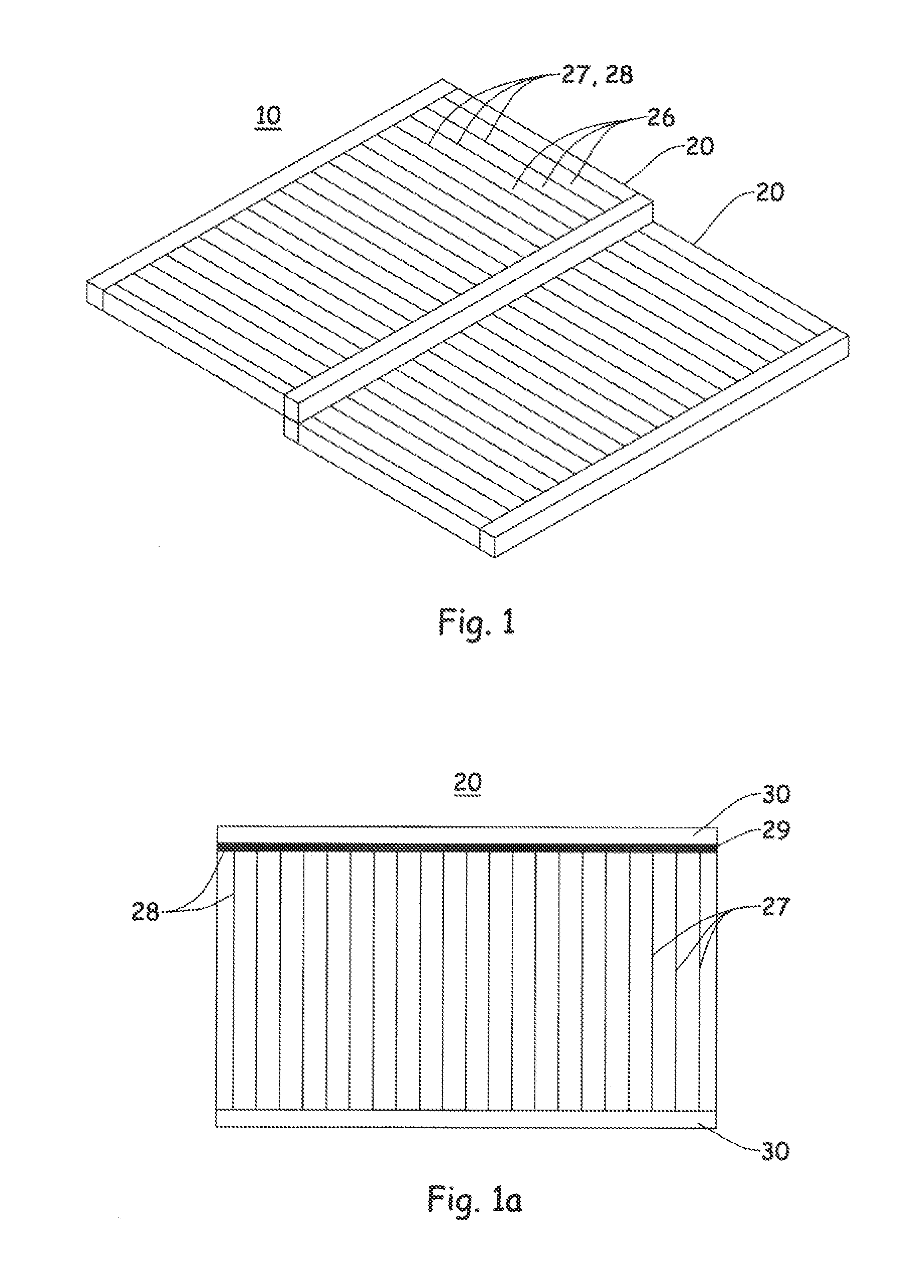
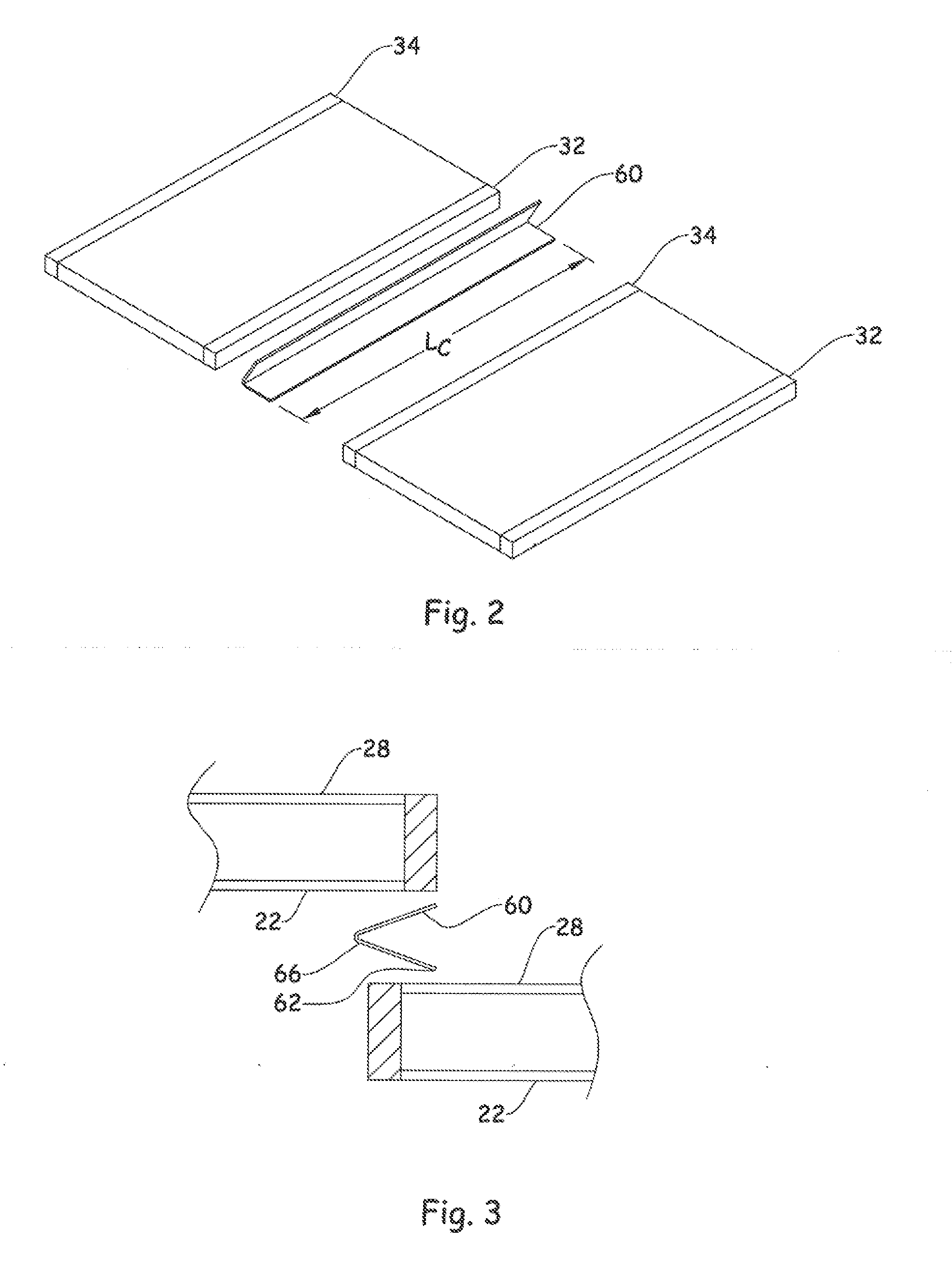
[0025]Of particular interest and the main focus of the present disclosure is an improved photovoltaic cell assembly 10 that includes at least a plurality of photovoltaic cells 20, and a conductive element 60, and optionally first and second encapsulant layers 40, 50. The conductive element 60 is folded or bent at least once and connects the conductive substrate 22 of one cell to the top conductive feature(s) 26 and / or 28 of an adjacent cell. In a preferred embodiment, the conductive element 60 is folded at least once along it...


PUM


Abstract

The present invention is premised upon an improved photovoltaic cell assembly that include at least plurality of photovoltaic cells with a photoactive portion with a top surface, a top collection structure on the top surface and an opposing conductive substrate layer on a side of the photoactive portion opposite the top surface. Also including a first conductive element with a first surface and wherein the first conductive element is bent at least once and wherein the first surface is in contact with the top collection structure and/or the top surface of a first photovoltaic cell and the opposing conductive substrate layer of an adjacent second photovoltaic cell; further wherein at least a portion of the first surface is held in contact to the cells by an adhesive.

Description

CLAIM OF PRIORITY[0001]The present application claims the benefit of the filing date of U.S. Provisional Application No. 61 / 38Q457 (filed 07-Sep.-2010) the contents of which are hereby incorporated by reference in their entirety.FIELD OF THE INVENTION[0002]The present invention relates to an improved photovoltaic (PV) cell assembly, more particularly to an improved photovoltaic cell assembly that interconnects a plurality of cells using a conductive element folded or bent to connect the bottom conductive substrate to the top conductive features of an adjacent cell.BACKGROUND[0003]Thin film solar cells provide several advantages especially when used in building integrated photovoltaic applications i.e. devices that are integrated into building structures for example as roofing shingles or exterior wall coverings. One such advantage is that these compositions have a high cross-section for absorbing incident light. That is, photovoltaic layers that are very thin can absorb and convert ...

Claims


Application Information

Patent Timeline
IPC IPC(8): H01L31/05H01L31/18
CPCY02E10/50H01L31/0508H02S40/36Y02B10/12H02S20/25H01L31/18Y02B10/10H01L31/05
Inventor DEGROOT, MARTYLANGLOIS, MARC GUY
Owner DOW GLOBAL TECH LLC
Why Eureka
Try Eureka