Multifunction printer and stopper applied therein

a multi-function printer and stopper technology, applied in the field of stoppers and multi-function printers, can solve the problems of high material cost and occupied space of office automation equipment, and achieve the effect of effective continuous operation

Inactive Publication Date: 2013-06-20
CAL COMP ELECTRONICS +1
View PDF2 Cites 1 Cited by
  • Summary
  • Abstract
  • Description
  • Claims
  • Application Information

AI Technical Summary

Benefits of technology

[0015]Based on the foresaid, the center of gravity of the stopper of the present invention is located in the eccentric portion. Since the center of gravity and the rotation center are located at two different positions when the stopper rotates about the rotating axle, the stopper is undoubtedly reposited by the aid of the weight of the stopper, so as to avoid the failure problem of the stopper. Therefore, the MFP using the stopper can effectively continuously operate.

Problems solved by technology

It should be noted that when being configured in the office at the same time, the office automation equipment occupies a lot of space.
In addition, two stoppers are required in such a design, so the material cost is high.

Method used


Image

  • Multifunction printer and stopper applied therein
  • Multifunction printer and stopper applied therein
  • Multifunction printer and stopper applied therein

Examples


Embodiment Construction

[0021]Reference will now be made in detail to the present embodiments of the invention, examples of which are illustrated in the accompanying drawings. Wherever possible, the same reference numbers are used in the drawings and the description to refer to the same or like parts.

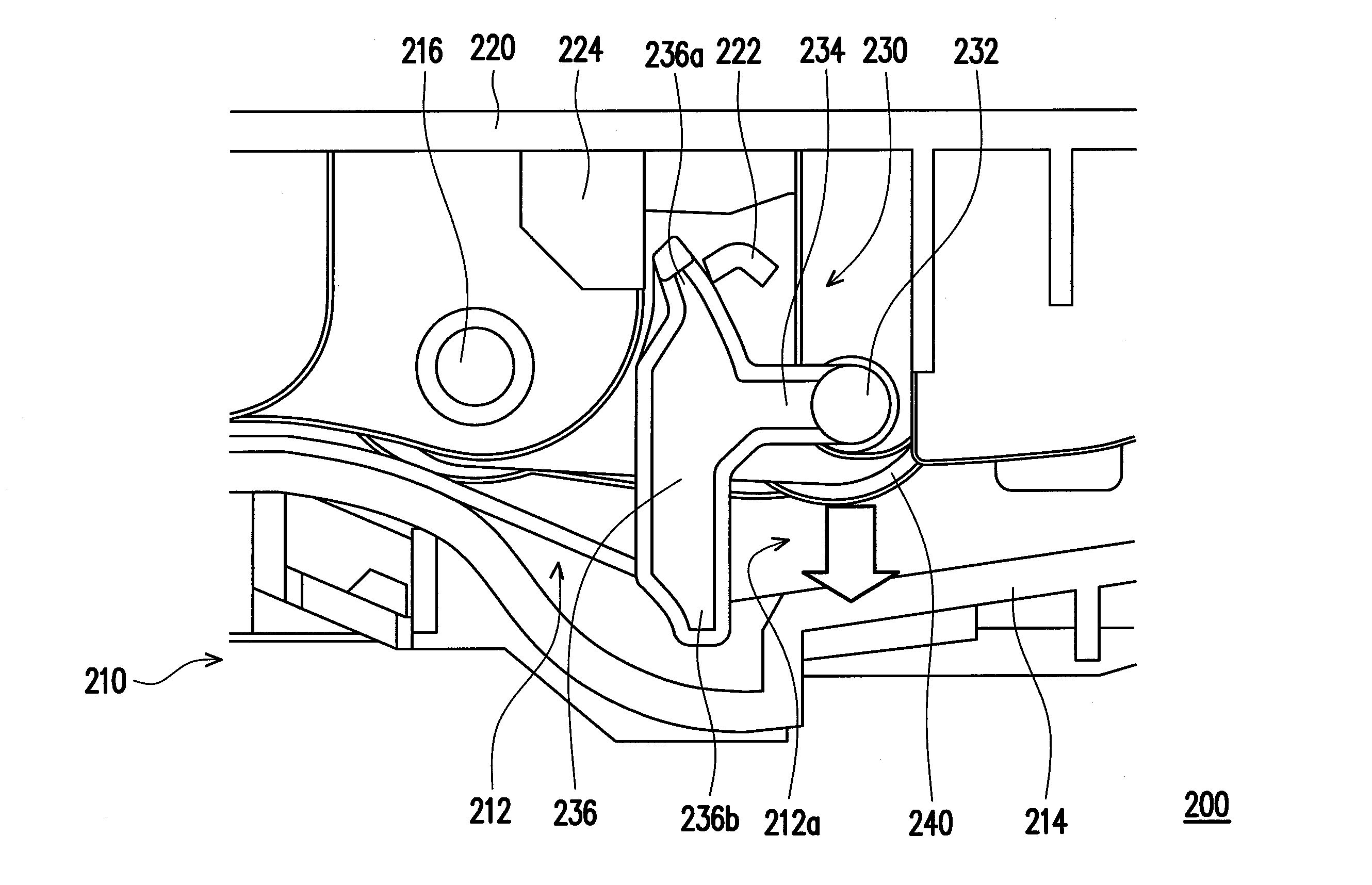
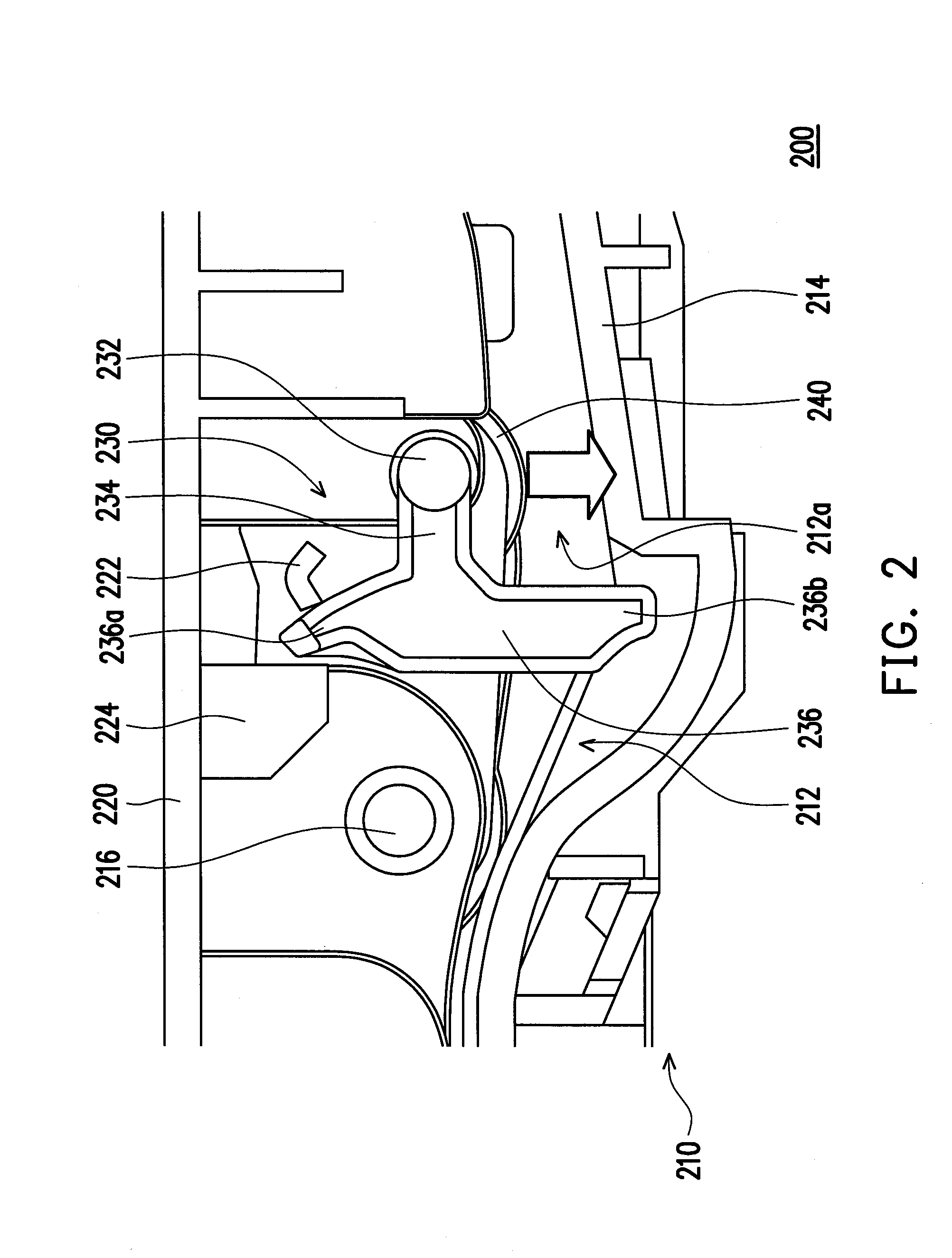
[0022]FIG. 2 is a schematic view of an MFP according to an embodiment of the present invention. Referring to FIG. 2, an MFP 200 includes a body 210, a top cover 220 and a stopper 230. The body 210 has a paper conveyor path 212, a paper holder 214, and a first rotating axle 216, in which the paper holder 214 is located in front of an entrance 212a of the paper conveyor path 212, and the first rotating axle 216 is located in the paper conveyor path 212. The top cover 220 is disposed on the body 210, and a first side (not shown) of the top cover 220 is adapted to rotate about the first rotating axle 216 so as to be close to the paper holder 214 of the body 210, in which the top cover 220 has a first stopping poin...


PUM


Abstract

A multifunction printer (MFP) and a stopper applied therein are provided. The MFP includes a body, a top cover and the stopper. The body has a paper conveyor path, a paper holder located in front of an entrance of the paper conveyor path and a first rotating axle located in the paper conveyor path. A first side of the top cover rotates about the first rotating axle to be close to the paper holder. The stopper has a second rotating axle connected to the body, a connecting portion and an eccentric portion. The connecting portion is connected between the second rotating axle and the eccentric portion. The eccentric portion hangs down at the entrance of the paper conveyor path. A center of gravity of the stopper is located in the eccentric portion. A first stopping point of the top cover is located in a rotating path of the eccentric portion.

Description

CROSS-REFERENCE TO RELATED APPLICATION[0001]This application claims the priority benefit of Taiwan application serial no. 100147468, filed on Dec. 20, 2011. The entirety of the above-mentioned patent application is hereby incorporated by reference herein and made a part of this specification.BACKGROUND OF THE INVENTION[0002]1. Field of the Invention[0003]The present invention relates to a stopper and a multifunction printer (MFP), and particularly to a stopper with a structure different from that of a conventional stopper and an MFP fitted with the stopper.[0004]2. Description of Related Art[0005]With the advent of the information society, an office may be provided with office automation equipment, for example, a scanner, a photocopier, or a printer, and a user may perform word processing operation by the aid of the office automation equipment. It should be noted that when being configured in the office at the same time, the office automation equipment occupies a lot of space. There...

Claims


Application Information

Patent Timeline
Patent Type & Authority Applications(United States)
IPC IPC(8): B65H7/00B65H3/06
CPCB65H3/0684B65H3/56B65H2801/06B65H3/34B65H2801/39
Inventor HSU, KAI-CHUANLEE, AN-HSIU
Owner CAL COMP ELECTRONICS
Why Eureka
Try Eureka