
Hydrostatically Powered Fracturing Sliding Sleeve

Active Publication Date: 2013-06-27
BAKER HUGHES INC
View PDF4 Cites 34 Cited by
  • Summary
  • Abstract
  • Description
  • Claims
  • Application Information

AI Technical Summary

Benefits of technology

The patent describes a device that uses sliding sleeves and a piston to open a port for fracturing even in the presence of cement in the annulus. The device is actuated by a single ball that shifts the ball seat to allow for communication of tubing pressure. The other side of the piston remains at atmospheric pressure so that the shifting of the ball seat not only releases the ball to go to the next ball seat but also puts a net force on the sliding sleeve to shift it against a travel stop to open the port for fracturing. The technical effect of this device is to allow for safe and effective fracturing in a variety of wellbore conditions.

Problems solved by technology

The risk in this system is that rupture discs sometimes have significant variability in their burst pressure so that a sleeve may shift at a time where it was not planned for it to shift.

Method used


Image

  • Hydrostatically Powered Fracturing Sliding Sleeve
  • Hydrostatically Powered Fracturing Sliding Sleeve
  • Hydrostatically Powered Fracturing Sliding Sleeve

Examples


Embodiment Construction

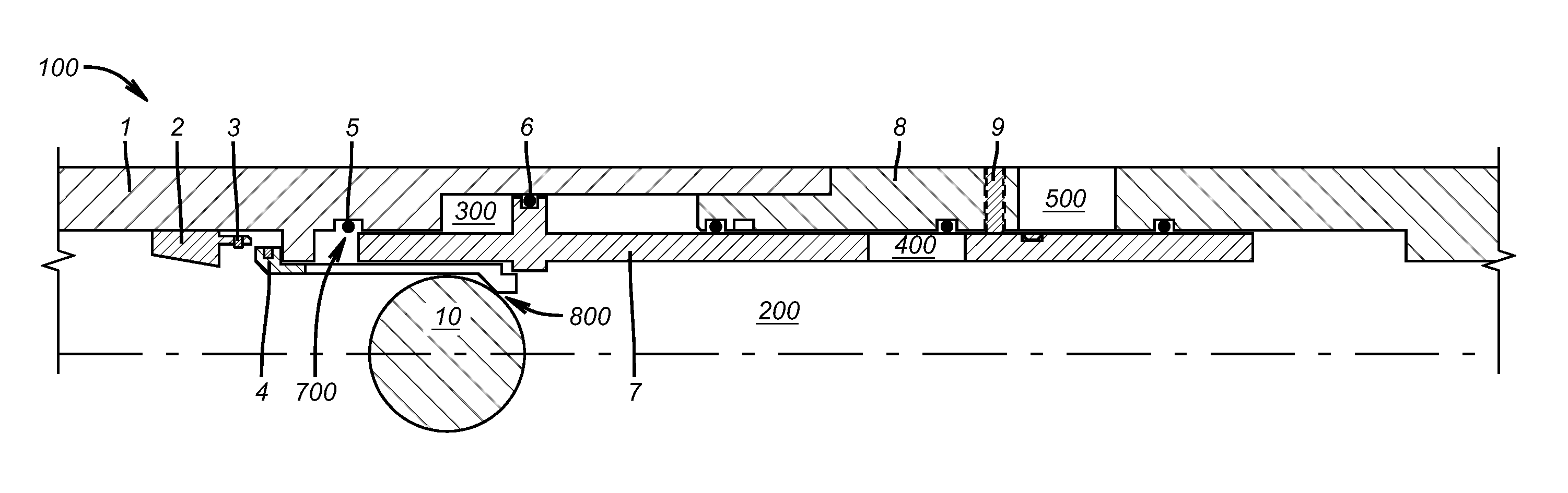
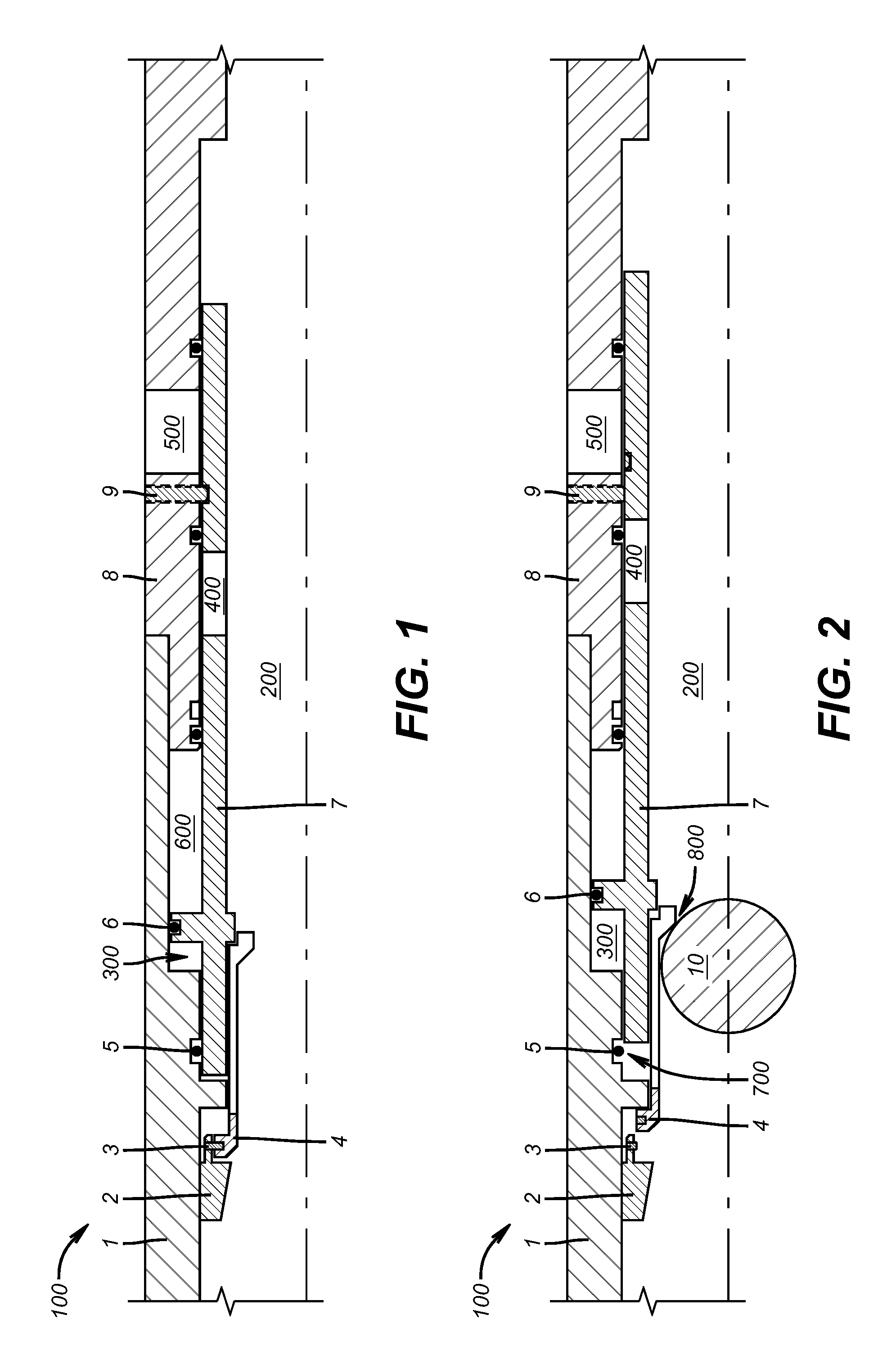
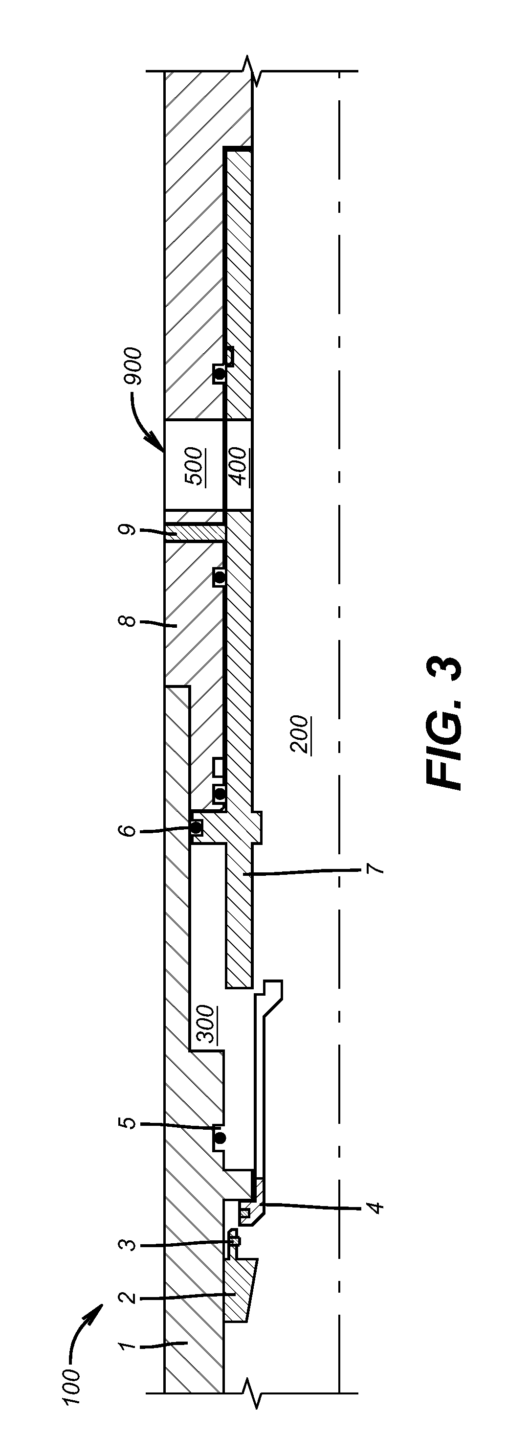
[0011]The tool run in hole in the closed position with ports 400 offset from ports 500 in the housing 1, 8. Two atmospheric chambers, 300 and 600, as shown in FIG. 1, are in pressure balance for running in. The surrounding annulus 12 can be cemented once the tool with a plurality of sleeve inserts or sliding sleeves 7 is properly placed at the desired subterranean location. Ball 10 is then dropped and lands on the collet 4, on ball seat profile 800, as shown in FIG. 2. Collet 4 moves down shearing shear screw 3. Collet 4 moves down and fully engages with sleeve insert 7 at 14. Collet 4 and sleeve insert 7 move down in tandem initially breaking shear screw 9. Collet 4 and sleeve insert 7 move down more and unload o-ring 5, opening flood path 700 into what was atmospheric chamber 300. Fluid from the tool inside diameter 200 floods atmospheric chamber 300 through flood path 700. Atmospheric chamber 600 contracts under influence of hydrostatic pressure and tubing pressure in now open ch...


PUM


Abstract

A series of sliding sleeves is actuated by a single ball that lands on a first ball seat and shifts the ball seat. The shifting of the ball seat also allows tubing pressure to communicate to a formerly atmospheric chamber on one side of a piston integrated into the back side of the sliding sleeve. The other side of the piston remains at atmospheric pressure so that the shifting of the ball seat not only releases the ball to go to the next ball seat but also puts a net force on the sliding sleeve to shift it against a travel stop to open a port to allow fracturing, even if there is cement in the annulus around the opened port.

Description

FIELD OF THE INVENTION[0001]The field of the invention is sliding sleeve operation at a subterranean location and more particularly operating multiple sliding sleeves with a common ball while getting a boost in the opening force from a piston exposed to higher pressure by ball seat movement that releases the ball.BACKGROUND OF THE INVENTION[0002]Access to a formation for fracturing is typically obtained with a series of sliding sleeves. The sleeves can come with a ball seat so that in some completions there can be as many as 40 balls of a gradually increasing diameter that need to be dropped in a specific order for opening the sleeves in a specific order going from downhole to uphole.[0003]More recently Baker Hughes has provided sliding sleeves with articulated ball seats so that a ball can land on a seat and shift a sliding sleeve and then the seat can open to allow the ball to pass further downhole to the hole bottom or to another ball seat on another sliding sleeve. This design i...

Claims


Application Information

Patent Timeline
IPC IPC(8): E21B34/14
CPCE21B34/103E21B34/14E21B43/26E21B34/142
Inventor KING, JAMES G.
Owner BAKER HUGHES INC
Features
  • Generate Ideas
  • Intellectual Property
  • Life Sciences
  • Materials
  • Tech Scout
  • Unparalleled Data Quality
  • Higher Quality Content
  • 60% Fewer Hallucinations
Learn More