
Electromechanical Excess Temperature Protection Element

a technology of excess temperature protection and electromechanical elements, applied in the direction of electrical apparatus, emergency protection arrangements for automatic disconnection, heating/cooling contact switches, etc., can solve the problems of limited safety precautions for photovoltaic systems in the open field, posed acute risk to emergency personnel or persons involved in accidents, and prone to hazards. , to achieve the effect of easy integration into the electrical circui

Inactive Publication Date: 2013-07-04
TOPINNO
View PDF5 Cites 4 Cited by
  • Summary
  • Abstract
  • Description
  • Claims
  • Application Information

AI Technical Summary

Benefits of technology

The invention is a safety device for photovoltaic and other electrical systems, designed to protect against excessive temperatures and mechanical impact. It is a permanent electric isolator that prevents any undesired shutoffs. The device contains a melting material that, when heated, pushes a cover plate out of a tube element, resulting in an isolated plug-in connector. This protective measure ensures that malfunctions are minimized, as the melting material is protected from weather exposure. The excess temperature protection element can be easily integrated into existing photovoltaic systems, providing a simple solution for safety compliance.

Problems solved by technology

Hazardous situations can arise, such as a fire on a roof structure on which a photovoltaic system is installed, or a collision of a motor vehicle with a PV system in an open field.
Such situations pose an acute risk for emergency personnel or persons involved in the accident, should they come into contact with life-threatening levels of electric voltages or currents in the modules.
Currently, safety precautions for photovoltaic systems in the open field are limited to a requirement that they be enclosed by a fence.
Thus far, there are no safety precautions for rooftop installations, because these are difficult to reach anyway.
Risk of injury to persons due to electric shock from photovoltaic systems, or in the worst case scenario, even death is rising, however, because of a steady increase in the number and size of photovoltaic systems.
The prior art provides few solutions that have the goal of reducing the risk of electric shock by photovoltaic systems, or which may at least be used for this purpose.
Although the safety device is in principle able to open circuits, even in case of a temperature rise resulting from a fire, it is not possible to achieve a safe and permanent isolation of voltages of up to 1000 V with the fuse device or thermostat switch.
Furthermore, both safety devices mentioned above have the disadvantage that they cannot be activated by a blow or an impact applied by emergency staff, as is often necessary in rescue missions.
The excess temperature protection element safely isolates the photovoltaic modules from each other during a fire, but it is not possible to mechanically deactivate the modules.
The solder joint connecting the two parts of the safety body is, however, subjected to environmental influences, such as temperature fluctuations, moisture, and UV radiation, in addition to the high, continuous forces caused by the spring, and, as a result, the solder joint often dissolves after only several months, leading to an uncontrolled and undesired shut-down of the photovoltaic modules.

Method used


Image

  • Electromechanical Excess Temperature Protection Element
  • Electromechanical Excess Temperature Protection Element

Examples


Embodiment Construction

[0030]The present invention will now be described more fully in detail with reference to the accompanying drawings, in which the preferred embodiments of the invention are shown. This invention should not, however, be construed as limited to the embodiments set forth herein; rather, they are provided so that this disclosure will be complete and will fully convey the scope of the invention to those skilled in the art.

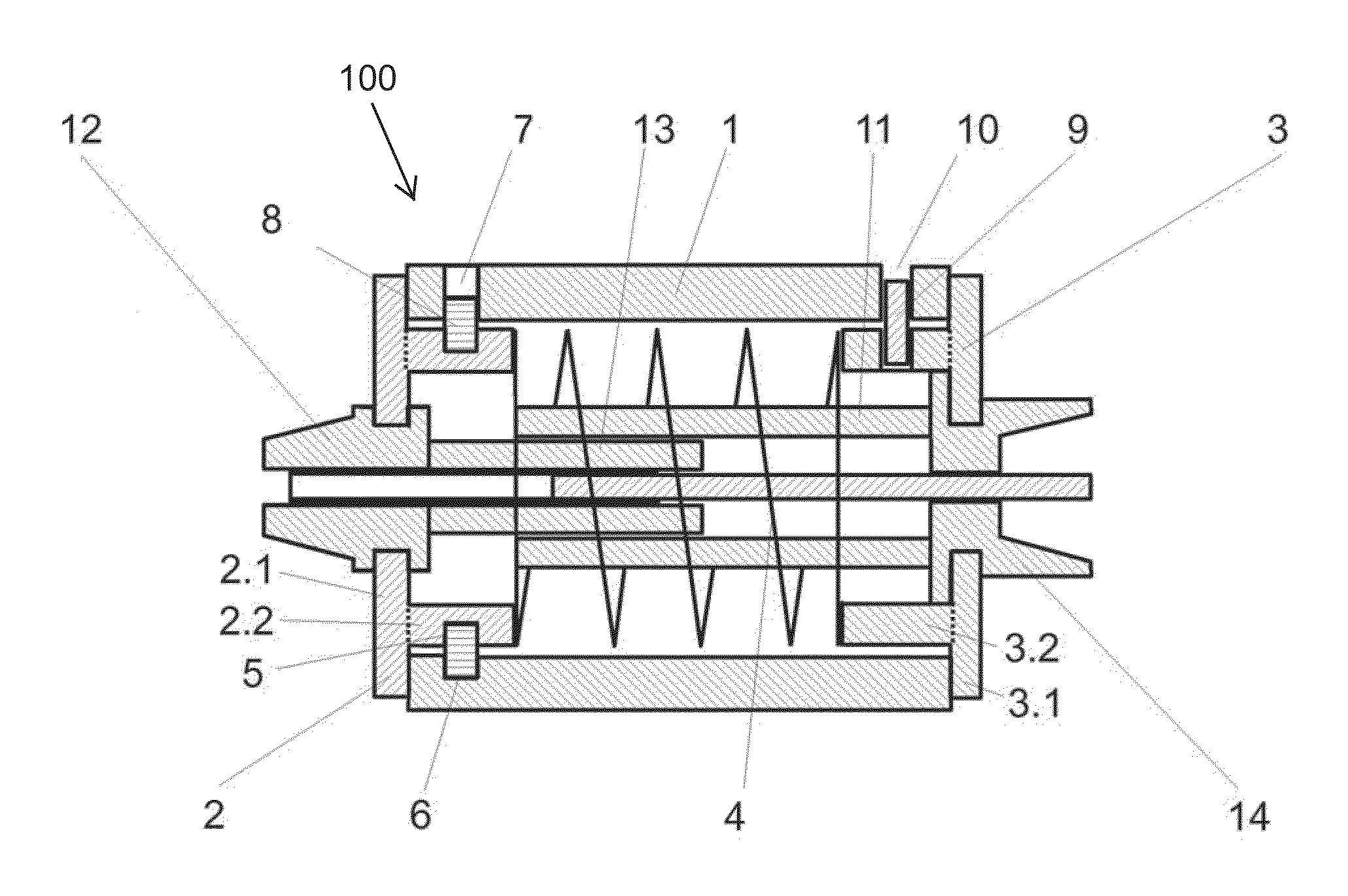
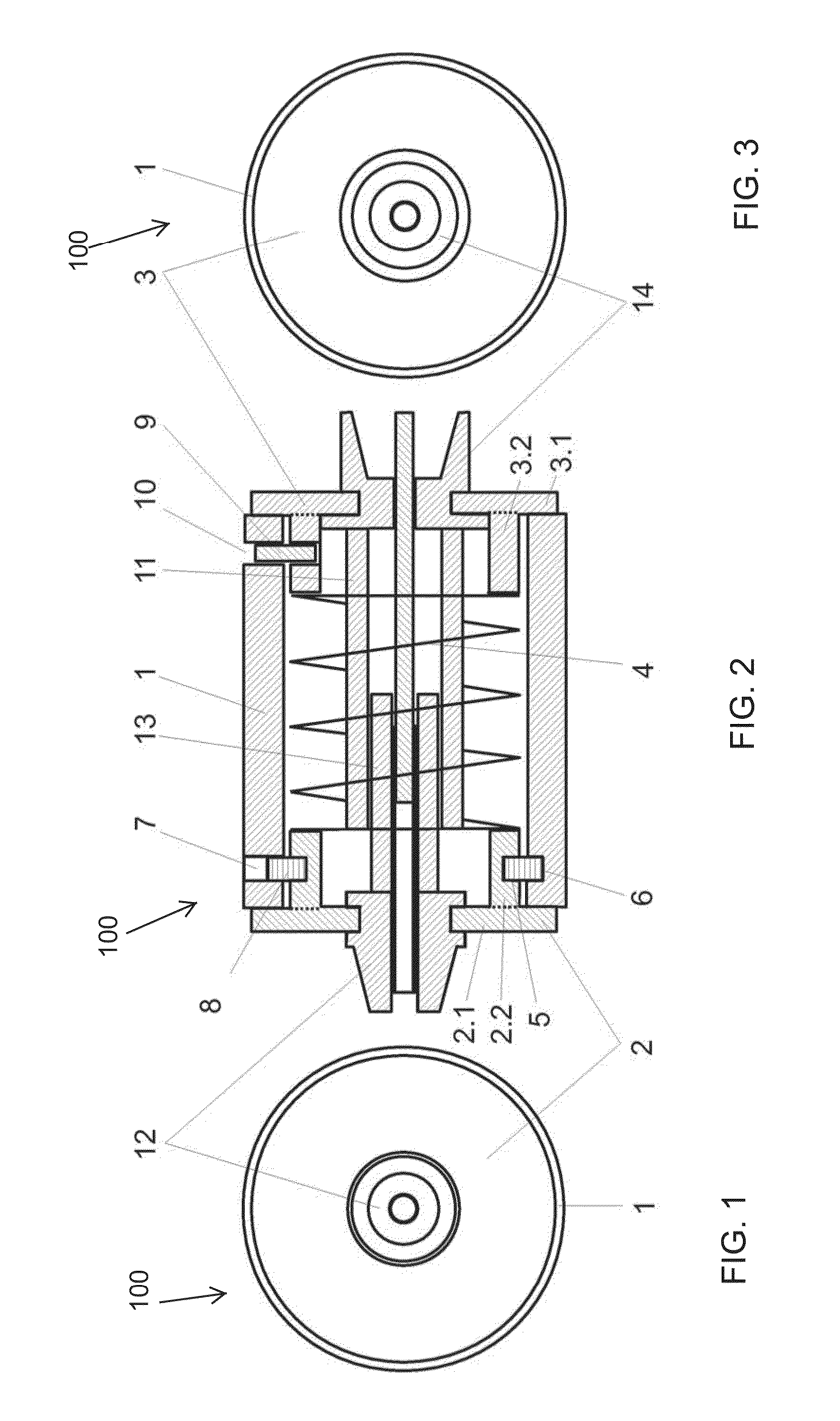
[0031]FIGS. 1-3 illustrate an excess temperature protection element 100 according to the invention. The excess temperature protection element comprises a housing 1, the end faces of which are closed by means of a releasable cover plate 2 and a fixed cover plate 3. The housing is constructed as a cylindrical tube with open end faces. The two cover plates 2, 3 have a first section 2.1, 3.1, respectively. Each first section completely covers the open end face of the housing 1. Extending from the first sections 2.1 and 3.1 are second sections or sidewalls 2.2 and 3.2, respec...


PUM


Abstract

The invention is an excess temperature protection element for photovoltaic installations. The element has a cylindrical housing closed off with two cover plates, encasing therein a plug-and-socket connection that is certified for photovoltaic installations. The plug connector is connected to the interior face of one cover plate and the socket connector to the interior face of the second cover plate, so that the two connectors are in electrical contact with each other when the housing is closed. A pressure element between the two cover plates biases the plates away from the housing. One of the plates is a releasable plate secured to the housing by a hot-melt material. When the temperature of the PV installation rises above a threshold value, the hot-melt material softens, allowing the pressure element to push the releasable cover plate away from the housing, thereby disconnecting the plug-in connection in the housing.

Description

BACKGROUND INFORMATION[0001]1. Field of the Invention[0002]The invention relates to an excess temperature protection element that is particularly suited for photovoltaic systems, but may also be used in other free wired electrical systems in interior and exterior areas.[0003]2. Discussion of the Prior Art[0004]In photovoltaic systems, an excess temperature protection element serves to electrically disconnect individual photovoltaic modules in hazardous situations. This excess temperature protection element also meets all electrical and safety technical requirements demanded of connector elements certified for operation in photovoltaic systems. The individual photovoltaic modules are usually series connected. At the end of the chain or string of modules, voltages of up to 1000 V DC voltage and currents of 8 to 16 A may occur when the sunlight is strong. Hazardous situations can arise, such as a fire on a roof structure on which a photovoltaic system is installed, or a collision of a ...

Claims


Application Information

Patent Timeline
IPC IPC(8): H02H5/04
CPCH02H5/04H01H37/76H01H37/765
Inventor WILLER, BERND
Owner TOPINNO
Learn More