Gasket structure of fuel cell separator with improved air tight seal

a fuel cell separator and gasket technology, which is applied in the direction of cell components, electrochemical generators, cell components, etc., can solve the problems of gasket burr, large portion of fuel cell stacks may be poorly sealed, and the gasket manufactured by a typical injection molding method has a limited amount of air tightness, so as to facilitate the flow of fluid, improve the air tight seal of each flow channel, and improve the effect of air tight seal

Active Publication Date: 2013-07-04
HYUNDAI MOTOR CO LTD +1
View PDF2 Cites 6 Cited by
  • Summary
  • Abstract
  • Description
  • Claims
  • Application Information

AI Technical Summary

Benefits of technology

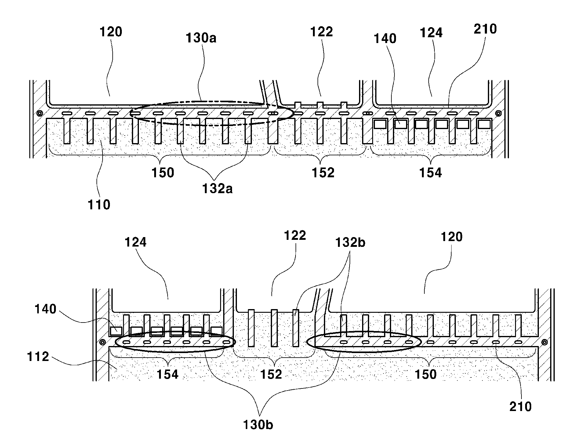
[0018]The present invention provides a gasket structure of a fuel cell separator having an improved air tight seal, which can improve the air tight seal of each flow channel without occurrence of minute deformation of the separator and burring of a gasket. The present invention also facilitates flow of fluid in each flow channel, by integrally forming a gasket structure on a portion of the fuel cell separator requiring an air tight seal.

Problems solved by technology

The gasket manufactured by a typical injection molding method has a limited amount of airtightness.
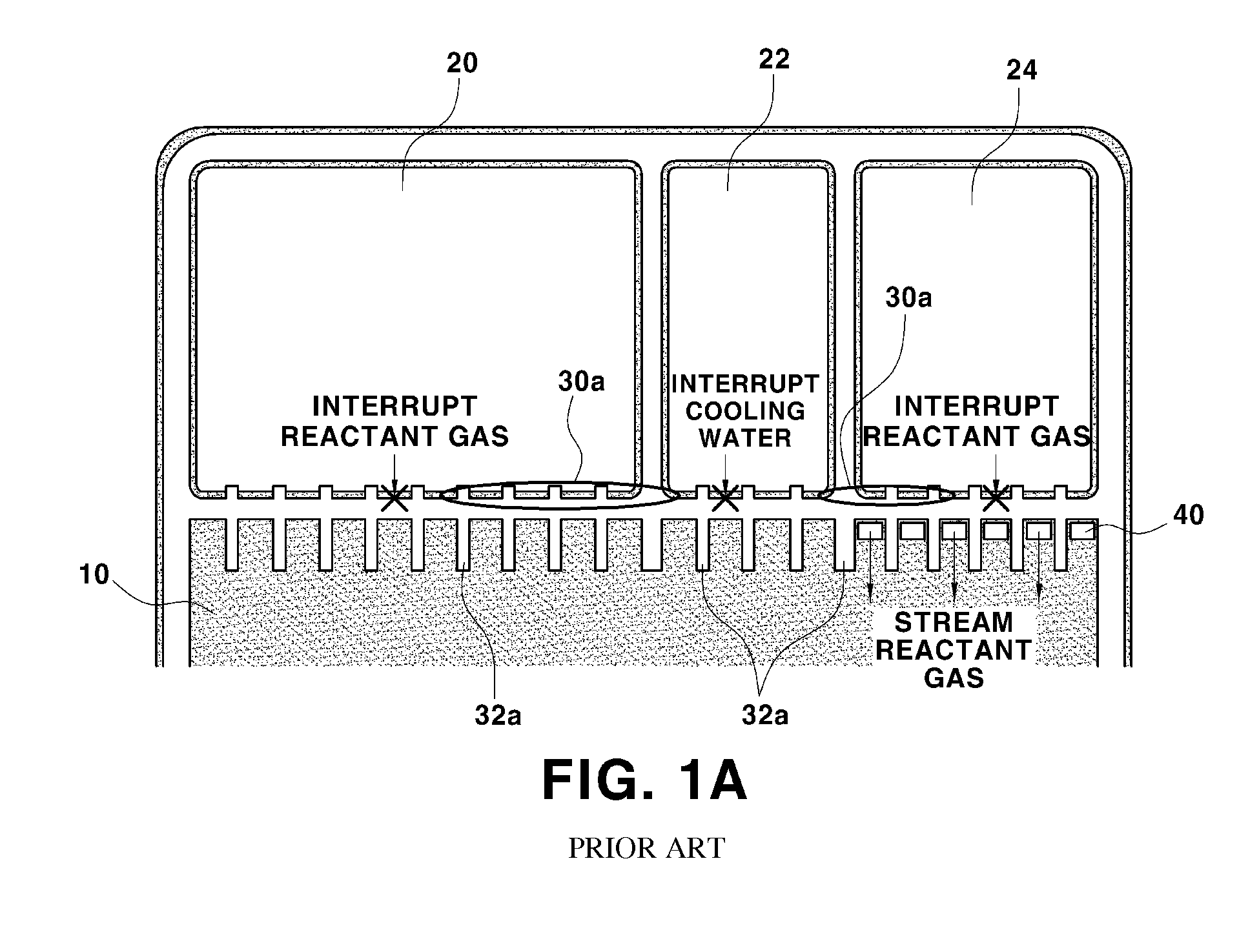
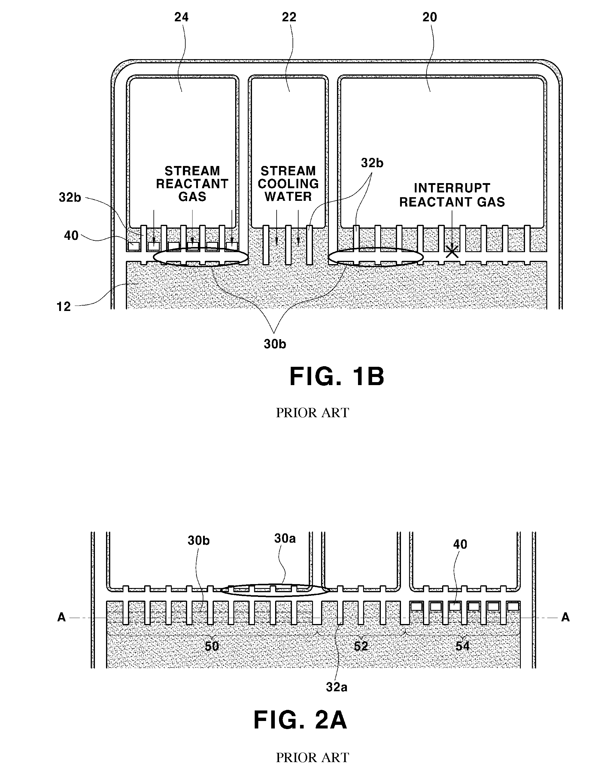
Thus, since different injection pressures are locally applied, a pressure applied in the arrow direction as indicated in the lower figured of FIG. 2B causes a minute deformation of the separator and thereby causing the gasket to burr.
The deformation of the separator and the burr of the gasket mean the vicinity of the gate of reactant gases cannot be uniformly compressed upon coupling of a fuel cell stack, and a considerable portion of fuel cell stack may as a result be poorly sealed.
Furthermore, the burr generated at the gate region of reactant gases results in the gasket being exposed to a hot and humid environment created by operation of a fuel cell.
As a result, the flow of reactant gases may be hindered, and the water discharging capacity may be reduced, causing the rapid reduction of the performance and the durability of the fuel cell.
Accordingly, when the gasket is integrally formed on the surface of the metal separator by a typical method, particularly, by injection molding, minute deformations of the separator and burrs in the gasket may occur.

Method used


Image

  • Gasket structure of fuel cell separator with improved air tight seal
  • Gasket structure of fuel cell separator with improved air tight seal
  • Gasket structure of fuel cell separator with improved air tight seal

Examples


Embodiment Construction

[0056]Hereinafter reference will now be made in detail to various embodiments of the present invention, examples of which are illustrated in the accompanying drawings and described below. While the invention will be described in conjunction with exemplary embodiments, it will be understood that present description is not intended to limit the invention to those exemplary embodiments. On the contrary, the invention is intended to cover not only the exemplary embodiments, but also various alternatives, modifications, equivalents and other embodiments, which may be included within the spirit and scope of the invention as defined by the appended claims.

[0057]It is understood that the term “vehicle” or “vehicular” or other similar term as used herein is inclusive of motor vehicles in general such as passenger automobiles including sports utility vehicles (SUV), buses, trucks, various commercial vehicles, watercraft including a variety of boats and ships, aircraft, and the like, and inclu...


PUM

PropertyMeasurementUnit
sizeaaaaaaaaaa
injection pressureaaaaaaaaaa
structureaaaaaaaaaa

Abstract

Disclosed is a gasket structure for a fuel cell separator with an improved air tight seal/sealability. The gasket structure includes first and second main lines and a plurality of sub lines. The first and second main lines are disposed in a horizontal direction in the separator on different lines of a reaction surface and a cooling surface of the separator, respectively. The plurality of sub lines are disposed in a vertical direction of the separator on both surfaces at a uniform interval. Here, the first and second main lines and the plurality of sub lines integrally form a gate for reactance gases and cooling water, and a plurality of vacant spaces are formed to have a uniform size on the first and second main lines.

Description

CROSS-REFERENCE TO RELATED APPLICATION[0001]This application claims under 35 U.S.C. §119(a) the benefit of Korean Patent Application No. 10-2011-0145373 filed Dec. 29, 2011, the entire contents of which are incorporated herein by reference.BACKGROUND[0002](a) Technical Field[0003]The present invention relates to a gasket structure of a fuel cell separator with an improved air tight seal. More particularly, it relates to a gasket structure of a fuel cell separator, which can an improve air tight seal of flow channels without occurrence of a gasket burr and facilitate flow of fluid in each flow channel, by forming a vacant space on a gasket formed integrally with the fuel cell separator.[0004](b) Background Art[0005]Generally, a metal separator manufactured by a method of, for example, stamping a thin metal plate has an advantage of significantly reducing the manufacturing time and cost compared to a graphite separator manufactured by mechanical working or powder molding. In a fuel ce...

Claims


Application Information

Patent Timeline
Patent Type & Authority Applications(United States)
IPC IPC(8): F16J15/02H01M8/02
CPCY02E60/50H01M8/04029H01M8/0276H01M8/0247H01M8/0267
Inventor JIN, SANG MUNYANG, YOO CHANG
Owner HYUNDAI MOTOR CO LTD
Why Eureka
Try Eureka