Optical element with lens barrel and manufacturing method thereof

A technology of optical components and manufacturing methods, which is applied in the directions of optical components, optics, installation, etc., can solve problems such as deterioration of the airtight seal of optical components, corrosion of stainless steel, and generation of rust, and achieve excellent airtight bonding and excellent airtight sealing effects

Active Publication Date: 2016-08-17
ALPS ALPINE CO LTD
View PDF6 Cites 0 Cited by
  • Summary
  • Abstract
  • Description
  • Claims
  • Application Information

AI Technical Summary

Problems solved by technology

In addition, when the laminated layer of stainless steel and nickel of different types of metals is exposed to air with moisture, the ionization of iron, which is the main component of stainless steel, is promoted, and corrosion may occur in stainless steel.
Furthermore, due to the corrosion of stainless steel, iron rust may be generated, and the peeling of the surface film 204 caused by the rust, the deterioration of the adhesion between the lens barrel 202 and the optical element 203 caused by the rust or the peeling of the surface film 204, etc.
[0023] Therefore, when the conventional optical element 201 with a lens barrel is used, there arises a problem that the airtight sealing of the optical module deteriorates.

Method used


Image

  • Optical element with lens barrel and manufacturing method thereof
  • Optical element with lens barrel and manufacturing method thereof
  • Optical element with lens barrel and manufacturing method thereof

Examples


no. 1 approach >

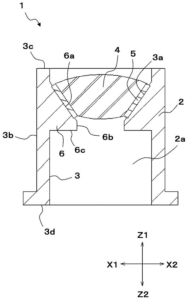
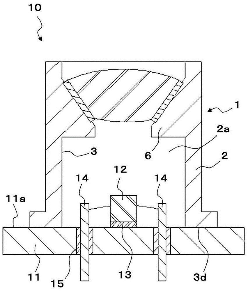
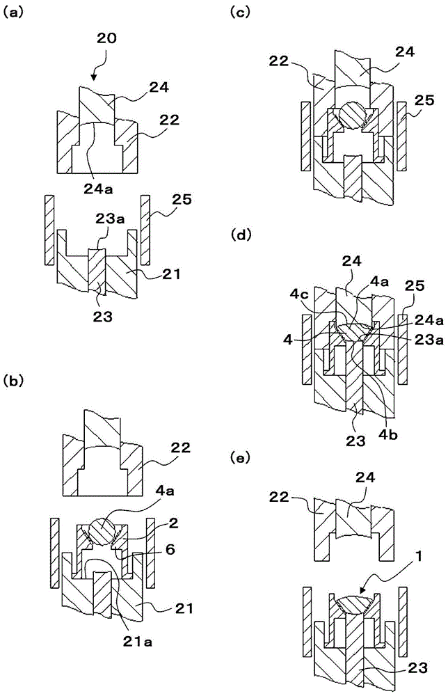
[0087] figure 1 It is a sectional view of the optical element with a lens barrel according to the first embodiment. figure 2 is a cross-sectional view of the optical module according to the first embodiment. image 3 It is explanatory drawing of the manufacturing method of the optical element with a lens barrel concerning 1st Embodiment. Figure 4 It is a partially enlarged cross-sectional view of the optical element with lens barrel according to the first embodiment.

[0088] Such as figure 1 As shown, the optical element 1 with a lens barrel according to the present embodiment is configured to include a lens barrel 2 and a lens 4 as an optical element. The lens barrel 2 is circular in plan view, formed in a cylindrical shape having a through hole 2 a , and has a protrusion 6 protruding inward from the inner peripheral surface 3 of the lens barrel 2 . The protrusion 6 has a surface continuously provided in the order of the protrusion slope 6a, the protrusion side surfa...

no. 2 approach >

[0128] Figure 6 It is a cross-sectional view of the optical element with lens barrel according to the second embodiment. In the optical element with lens barrel 31 according to the second embodiment, as Figure 6 As shown, the metal oxide layer 5 is laminated on the entire surface of the inner peripheral surface 3 of the lens barrel 2 . Furthermore, the metal oxide layer 5 is sequentially stacked with a first metal oxide layer made of chromium (Cr) oxide and a second metal oxide layer made of iron (Fe) oxide.

[0129] The optical element with a lens barrel 31 according to the present embodiment is different from the optical element with a lens barrel 1 according to the first embodiment in that, compared to the optical element with a lens barrel 1 , only the figure 1 The second metal oxide layer is formed in the region of the barrel joint surface 3 a shown in FIG. Regarding other points, the two optical elements with lens barrels 1 and 31 have substantially the same configur...


PUM


Abstract

PROBLEM TO BE SOLVED: To provide an optical element with a lens tube having good hermetic bonding between the lens tube and the optical element and excellent hermetic seal of an optical module, and a method of manufacturing the same.SOLUTION: An optical element 1 with a lens tube includes a metal lens tube 2 and an optical element 4 subjected to hermetic bonding with an inner peripheral surface 3 of the lens tube 2. A metal oxide layer 5 containing at least one element of iron, cobalt, nickel, and copper is formed on the surface of the lens tube 2. A lens tube composition surface 3a is an area on a surface in contact with the optical element 4. The thickness of the metal oxide layer 5 formed on the lens tube composition surface 3a is thicker than the thickness of the metal oxide layer 5 formed on the surface of the lens tube 2 excluding the lens tube composition surface 3a.

Description

technical field [0001] The present invention relates to an optical element with a lens barrel integrally formed with an optical element and a manufacturing method thereof, and more particularly to an optical element with a lens barrel used in an optical module in which a light-emitting element is hermetically sealed and a manufacturing method thereof. Background technique [0002] Conventionally, in the fields of optical communication and the like, there are known optical devices with lens barrels that accommodate light-emitting elements that emit light and convert the emitted light from the light-emitting elements into parallel light or condense them on optical fibers or the like. components. At this time, in order to prevent oxidation of the output portion of the light emitting element, the light emitting element is hermetically sealed in an optical module filled with an inert gas such as nitrogen. [0003] Figure 8 It is a cross-sectional perspective view of an optical ...

Claims


Application Information

Patent Timeline
Patent Type & Authority Patents(China)
IPC IPC(8): G02B7/02
Inventor 菊池俊宏近藤康之山谷政崇川田贞夫
Owner ALPS ALPINE CO LTD
Why Eureka
Try Eureka