Wear assembly

a technology for wearing parts and assembly, applied in soil shifting machines/dredgers, constructions, etc., can solve the problems of wear parts that are typically subject to heavy loading and high abrasion conditions

Active Publication Date: 2013-07-11
ESCO GRP LLC
View PDF10 Cites 60 Cited by
  • Summary
  • Abstract
  • Description
  • Claims
  • Application Information

AI Technical Summary

Benefits of technology

[0012]In another aspect of the invention, a lock for releasably securing a wear member to earth working equipment includes a threaded pin with a socket in one end for receiving a too

Problems solved by technology

During use, the wear parts typically encounter

Method used


Image

  • Wear assembly
  • Wear assembly
  • Wear assembly

Examples


Embodiment Construction

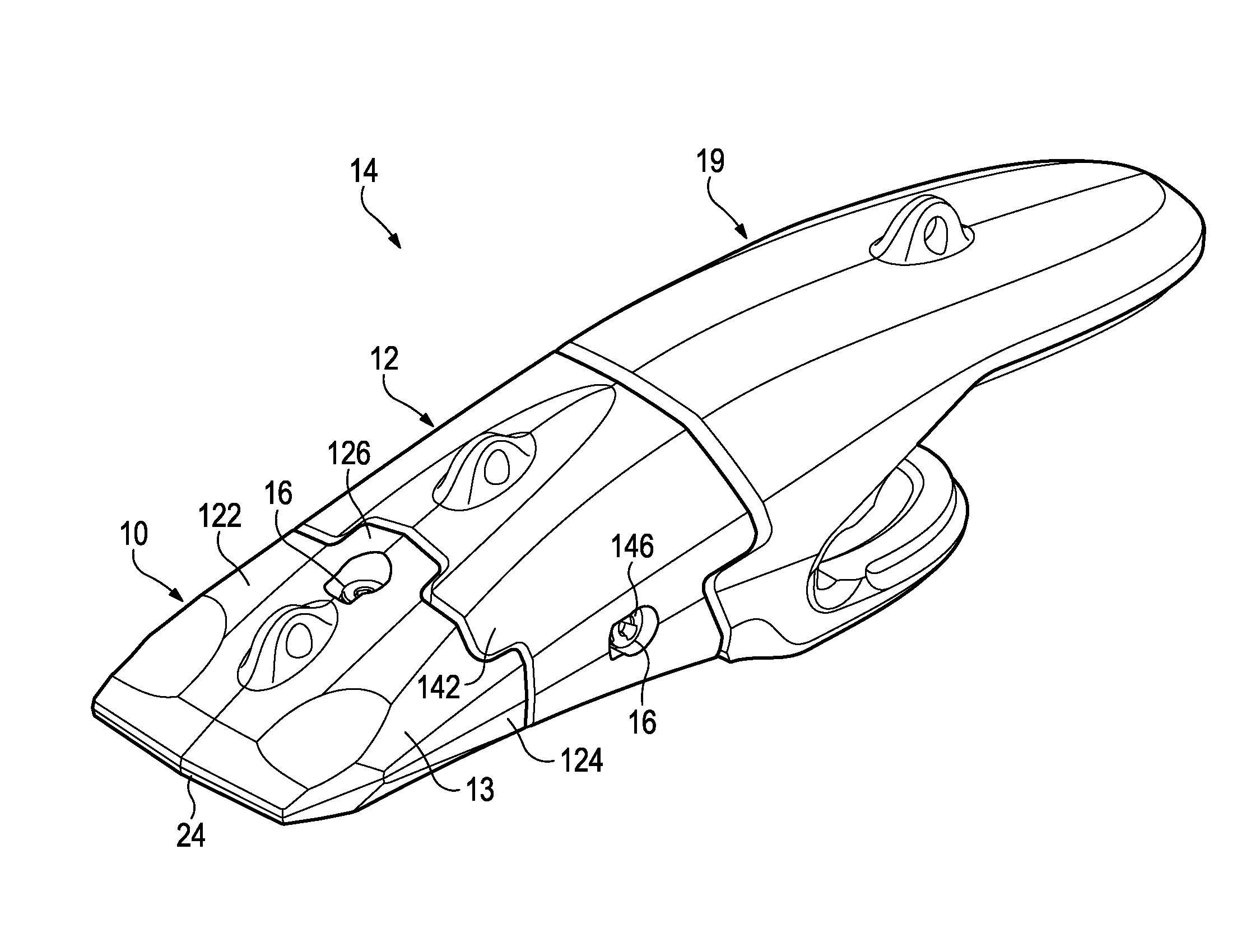
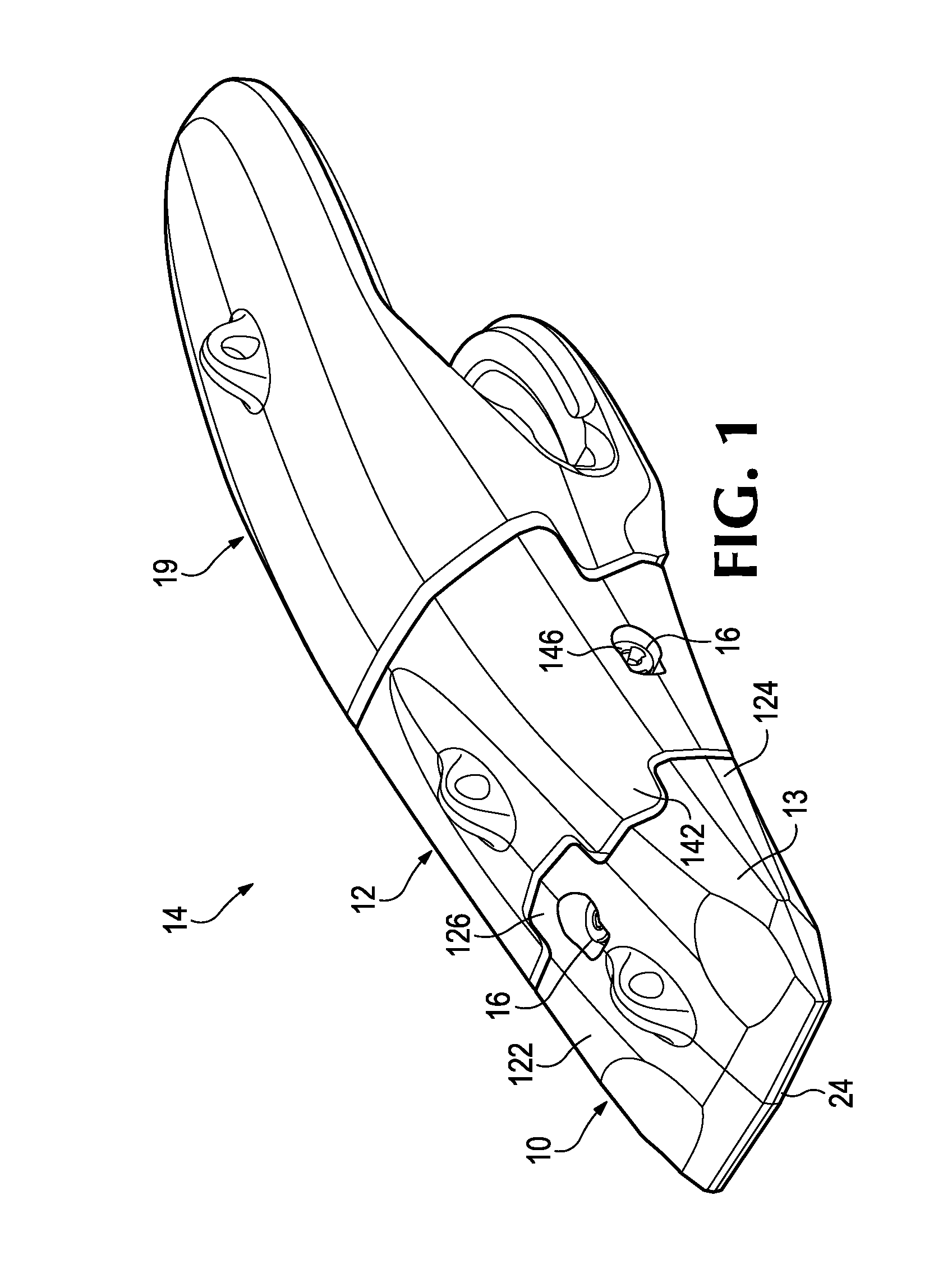
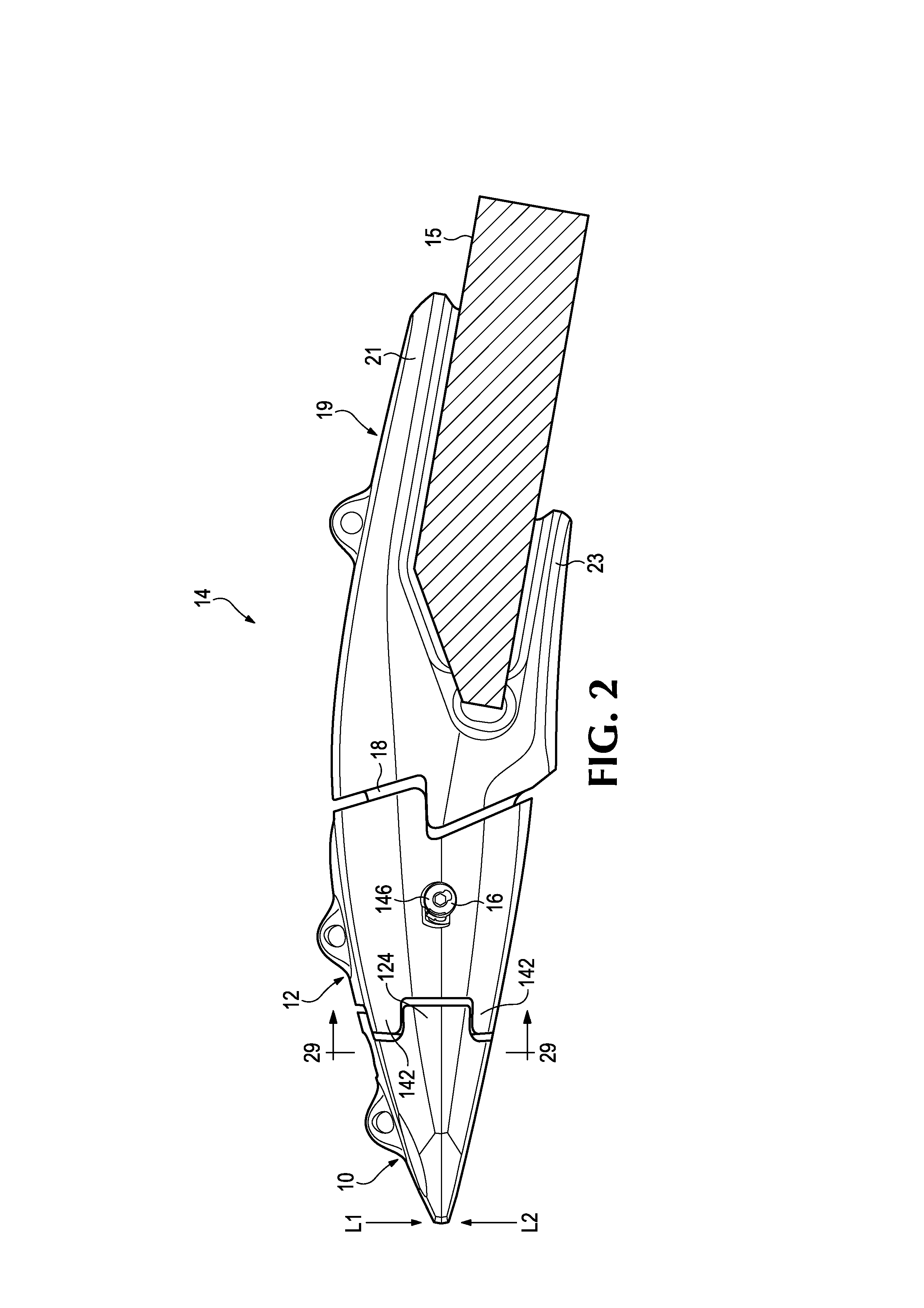
[0057]The present invention pertains to a wear assembly for various kinds of earth working equipment including, for example, excavating equipment and ground conveying equipment. Excavating equipment is intended as a general term to refer to any of a variety of excavating machines used in mining, construction and other activities, and which, for example, include dragline machines, cable shovels, face shovels, hydraulic excavators, and dredge cutters. Excavating equipment also refers to the ground-engaging components of these machines such as the bucket or the cutter head. The digging edge is that portion of the equipment that leads the contact with the ground. One example of a digging edge is the lip of a bucket. Ground conveying equipment is also intended as a general term to refer to a variety of equipment that is used to convey earthen material and which, for example, includes chutes and mining truck beds. The present invention is suited for use along the digging edge of excavatin...


PUM


Abstract

A wear assembly for use on various kinds of earth working equipment that includes a base with a supporting portion, a wear member with a cavity into which the supporting portion is received, and a lock to releasably secure the wear member to the base. The supporting portion is formed with top and bottom recesses that receive complementary projections of the wear member. These recesses and projections include aligned holes so as to receive and position the lock centrally within the wear assembly and remote from the wear surface. The lock includes a mounting component that defines a threaded opening for receiving a threaded pin that is used to releasably hold the wear member to the base. The separate mounting component can be easily manufactured and secured within the wear member for less expense and higher quality than forming the threads directly in the wear member.

Description

FIELD OF THE INVENTION[0001]The present invention pertains to a wear assembly for use on various kinds of earth working equipment.BACKGROUND OF THE INVENTION[0002]In mining and construction, wear parts are commonly provided along the digging edge of excavating equipment such as buckets for dragline machines, cable shovels, face shovels, hydraulic excavators, and the like. The wear parts protect the underlying equipment from undue wear and, in some cases, also perform other functions such as breaking up the ground ahead of the digging edge. During use, the wear parts typically encounter heavy loading and highly abrasive conditions. As a result, they must be periodically replaced.[0003]These wear parts usually comprise two or more components such as a base that is secured to the digging edge, and a wear member that mounts on the base to engage the ground. The wear member tends to wear out more quickly and is typically replaced a number of times before the base must also be replaced. O...

Claims


Application Information

Patent Timeline
IPC IPC(8): E02F9/28
CPCE02F9/2841E02F9/2883E02F9/2858E02F9/28E02F9/2825E02F9/2833E02F9/267
Inventor CHEYNE, MARK A.COWGILL, NOAHROSKA, MICHAEL B.CONKLIN, DONALD M.ZENIER, SCOTT H.HAINLEY, CHRIS J.
Owner ESCO GRP LLC
Why Eureka
Try Eureka