Retrofittable interstage angled seal

Inactive Publication Date: 2013-07-25
GENERAL ELECTRIC CO
View PDF4 Cites 11 Cited by
  • Summary
  • Abstract
  • Description
  • Claims
  • Application Information

AI Technical Summary

Benefits of technology

This patent describes a method for reducing a gap between rotating and stationary components of a turbine. This is achieved by using a combination of an angel wing seal and an abradable seal. The angel wing seal is supported by a stator component and is designed to allow for axial growth of the rotor. The abradable seal is positioned at an angle to the angel wing seal to minimize the gap between them. This technique can improve the efficiency of the turbine and reduce the amount of air that leaks through the gap, resulting in higher power output and improved performance.

Problems solved by technology

If the clearance is too large, excessive and valuable cooling air will leak through the gap, decreasing the turbine's efficiency.
If the clearance is too small, the angel wing tip(s) will strike the sealing structure of the adjacent stator component during certain turbine operating conditions, causing undesirable wear on both the angel wing tip(s) and the stationary stator component(s).
During periods of differential centrifugal force, rotor vibration, and thermal growth, the clearance changes can result in severe rubbing of the rotating bucket angel wing seal tips against the stationary seal structures.
Increasing the tip-to-seal clearance gap reduces the damage due to metal to metal rubbing, but the increase in clearance results in efficiency loss.

Method used


Image

  • Retrofittable interstage angled seal
  • Retrofittable interstage angled seal
  • Retrofittable interstage angled seal

Examples


Embodiment Construction

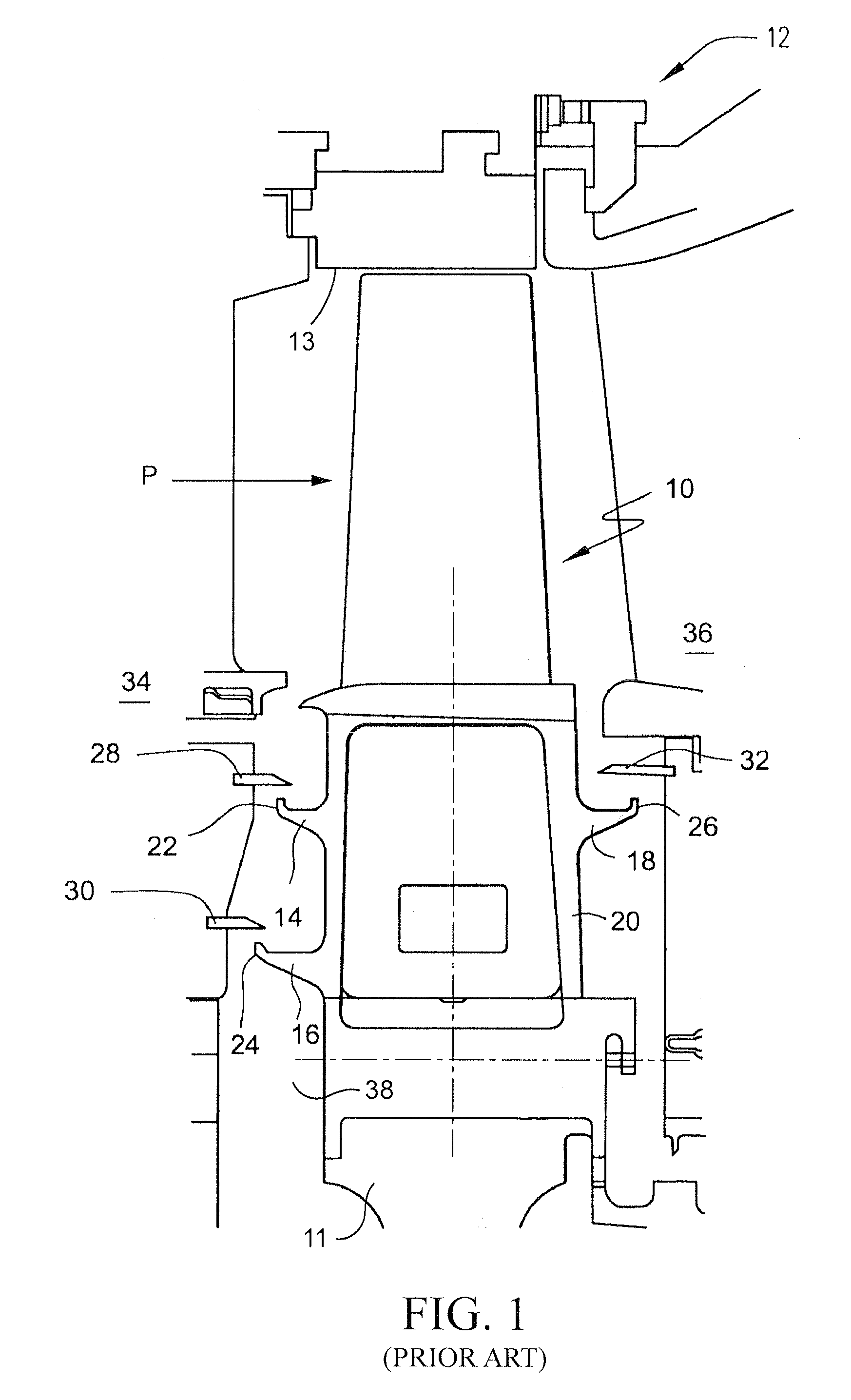
[0015]FIG. 1 is a cross-sectional view which shows a conventional seal assembly for preventing or limiting cooling air from leaking from between a moving blade (or bucket) and a stationary blade (or nozzle) of a gas turbine into the high temperature combustion gas passage. The turbine of this example embodiment has a rotor or shaft (not shown in detail) rotatable about a center longitudinal axis and a plurality of blades or buckets 10 fixedly mounted on the outer annular surface of a disk 11 supported on the rotor. Typically, the buckets include a mounting portion, a shank and an airfoil. The buckets are spaced from one another circumferentially about, and extend radially outward from the outer annular surface of the rotor disk to end tips of the bucket airfoils. An outer casing 12 having a generally annular and cylindrical shape and an inner circumferential surface 13 is stationarily disposed about and spaced radially outwardly from the buckets 10 to define the axially-oriented hig...


PUM


Abstract

A rotary turbomachine includes a rotor mounting at least one disk having an outer surface and at least one bucket extending radially from said outer surface. A stationary stator component is located adjacent the disk, and a seal plate extends from a portion of the stationary stator component. An angel wing seal extends from the bucket, thereby defining a clearance gap between the seal plate and the angel wing seal. An abradable seal element is disposed on the seal plate, and the abradable seal element and the seal plate are canted at an acute angle relative to a center axis of the rotor extending radially outwardly in a direction toward the angel wing seal.

Description

BACKGROUND OF THE INVENTION[0001]The present invention generally relates to rotary machines such as steam and gas turbines and, more particularly, to a rotary machine seal for controlling clearance between the shank portions of rotating rotor blades or “buckets” and radially inner ends of adjacent, stationary stator components.[0002]Land-based steam and gas turbines are used, for example, to power electric generators. Gas turbines are also used, for example, to propel aircraft and ships. A steam turbine has a steam path which typically includes in serial-flow relation, a steam inlet, a turbine, and a steam outlet. A gas turbine has a gas path which typically includes, in serial-flow relation, an air intake or inlet, a compressor, a combustor, a turbine, and a gas outlet or exhaust nozzle. In both steam and gas turbines, compressor and turbine sections include at least one circumferential row of rotating blades or buckets mounted on rotor wheels or disks. The free ends or tips of the...

Claims


Application Information

Patent Timeline
IPC IPC(8): F01D11/00
CPCF01D11/125F01D11/122F01D11/001F01D11/127F05D2250/38
Inventor ADAICKALASAMY, JAMES
Owner GENERAL ELECTRIC CO
Why Eureka
Try Eureka