Calorific equipment equipped with coaxial heat exchanger

A technology of heat exchangers and equipment, applied in the field of thermal equipment, can solve the problems of lack of elasticity of non-hermetic sealing materials, wear of sealing materials, and inability to be compensated

Inactive Publication Date: 2017-05-24
CHOREN INDTECHN
View PDF9 Cites 0 Cited by
  • Summary
  • Abstract
  • Description
  • Claims
  • Application Information

AI Technical Summary

Problems solved by technology

If hard sliding seal materials are used, manufacturing tolerances, in particular shape deviations of the welded pipe, lead to leaks which cannot be compensated due to the lack of elasticity of the seal material
According to DE 20 2007 011 109 U1 or DE 20 2007 018 720 U1, when sof

Method used


Image

  • Calorific equipment equipped with coaxial heat exchanger
  • Calorific equipment equipped with coaxial heat exchanger
  • Calorific equipment equipped with coaxial heat exchanger

Examples


Embodiment Construction

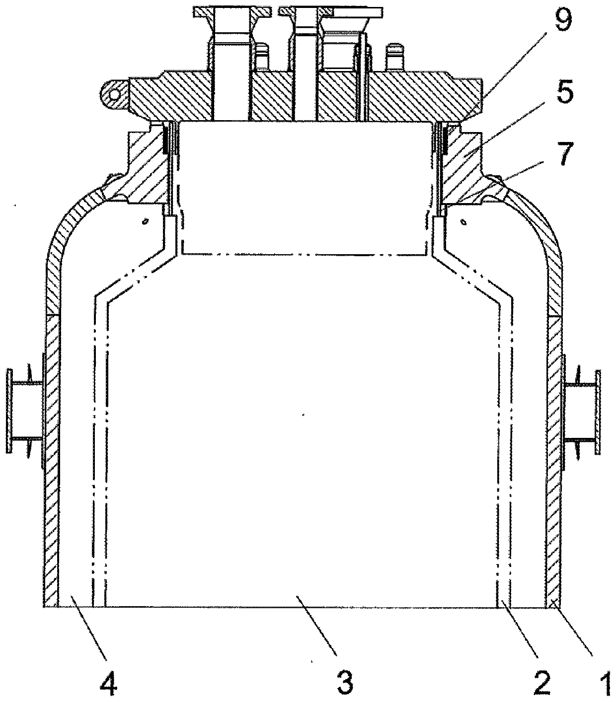
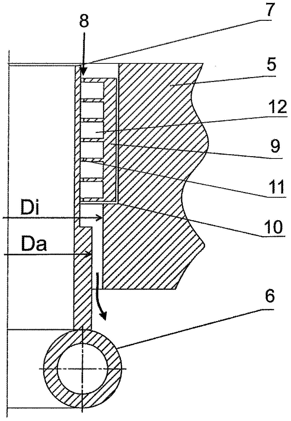
[0025] exist figure 1 In the upper section of a cylindrical gasification reactor with a pressure-tightly closable pressure enclosure 1 shown in , an internal, near-wall heat exchanger 2 (in the gas In the case of chemical reactors, known as cooling screens) are arranged coaxially. The cooling screen is supported on a device bottom (not shown) and forms an annular space 4 opposite the pressure housing 1, wherein the pressure housing 1 has a closable cover flange 5 opposite to the is arranged centrally on the axis of the device and has an inner diameter Di ( figure 2 ).

[0026] The cover flange 5 (which generally also serves to receive the holder of the gasification combustion chamber) is pressure-tightly closed with a flange cover (no reference symbol).

[0027] as from figure 2 As can be seen in the sectional illustration in , the heat exchanger 2 has a plurality of gas-tightly connected coolant channels (here symbolically represented by an upper cooling tube 6 ) and a ...


PUM


Abstract

The invention relates to calorific equipment equipped with a coaxial heat exchanger. The calorific equipment is provided with a pressure shield which is pressureably closed at the flange of a cover plate and is provided with a coaxial, internal heat exchanger which surrounds an internal space and forms an annular space relative to the pressure shield. The object of the present invention is based on the provision of a structural solution for configuring an annular gap between the heat exchanger and the equipment wall (which has a long use time) for transmitting pressure and located in the area of the flange of the cover plate. The object is achieved by providing a maze-type sealed part for loading a purge gas in the annular gap between flange of the cover plate and a tube located at the center of the upper part of the heat exchanger.

Description

technical field [0001] The invention relates to a thermal device with a pressure-tightly closable pressure enclosure and with a coaxial, internal heat exchanger, which surrounds an internal space, supported on a device bottom and form an annular space relative to the pressure housing. Background technique [0002] A thermal device of this type usually has a pressure housing with a closable cover flange, which is arranged centrally with respect to the device axis and has a corresponding inner diameter. Furthermore, the heat exchanger has at its end facing the cover flange an upper pipe piece which has an outer diameter which is smaller than the inner diameter of the cover flange. The upper tube extends vertically into the cover flange. An overpressure can be built up in the annular space relative to the reaction space with a purge gas. [0003] When sealing pressurized spaces, there is often the problem that parts adjoining each other at the sealing point expand differentl...

Claims


Application Information

Patent Timeline
IPC IPC(8): C10J3/00C10J3/74
CPCC10J3/00C10J3/74
Inventor 法比安·艾佐尔德
Owner CHOREN INDTECHN
Why Eureka
Try Eureka