Mechanical seal device

a mechanical seal and sealing technology, applied in the direction of engine seals, basic electric elements, electrical apparatus, etc., can solve the problems of insufficient floating force, vibration in the behavior adversely affecting the product, etc., to suppress the vibration the contact between the seal surfaces, prevent the incorporation of abrasion powder, and suppress the effect of the rotational seal ring vibration

Active Publication Date: 2010-06-29
EAGLE INDS
View PDF15 Cites 26 Cited by
  • Summary
  • Abstract
  • Description
  • Claims
  • Application Information

AI Technical Summary

Benefits of technology

[0012]An object of the present invention is to provide a mechanical seal device capable of preventing incorporation of an abrasion powder to a sealed fluid by suppressing vibration of a rotational seal ring and preventing contact between seal surfaces.
[0021]Also, in the present invention, two or more arc-shaped grooves are formed on the rotational seal surface and adjacent arc-shaped grooves are sectionalized by a partition wall. As a result, even when one seal surface tilts with respect to the other seal surface, a pressure becomes high in arc-shaped grooves positioned on the side with a narrowed space between the seal surfaces and the pressure acts as a recovery force for recovering the tilt, so that contact between the seal surfaces is prevented.
[0022]Furthermore, in the present invention, a circumferential direction length (W3) of each of the outlet portions is made to be ½ of a circumferential direction length (W1) of each of the partition walls or longer (W3≧W1 / 2). As a result, a sufficient floating force can be secured and a non-contact state between the seal surfaces can be preferably maintained.
[0026]the circumferential direction length (W3) of the outlet portions is made to be shorter than ½ of a circumferential direction length (W2) of the arc-shaped grooves (W3<W2 / 2). As a result, vibration of the rotational seal ring and contact between the seal surfaces can be suppressed effectively.
[0028]In the mechanical seal device according to claim 4, the partition walls are formed to be relatively lower than the rotational seal surface and relatively higher than bottom surfaces of the arc-shaped grooves. As a result, vibration of the rotational seal ring and contact between the seal surfaces can be suppressed effectively.
[0029]As explained above, according to the present invention, contact between the rotational seal surface and the stationary seal surface can be suitably prevented while suppressing the Pneumatic Hammer phenomenon caused by a compressibility of a pressure fluid. Accordingly, it is possible to provide a mechanical seal device capable of preventing incorporation of an abrasion powder to a sealed fluid by suppressing vibration of the rotational seal ring and preventing contact between the seal surfaces.

Problems solved by technology

In semiconductor production facilities, etc., when an impurity is included in a sealed fluid, it adversely affects the products.
However, as the volume of the grooves formed on the stationary seal surface increases, vibration arises in a behavior of the rotational seal ring.
On the other hand, when the volume of the grooves formed on the stationary seal surface is decreased to suppress the Pneumatic Hammer phenomenon, a sufficient floating force cannot be obtained and the rotational seal surface contacts with the stationary seal surface.
Therefore, there is almost no volume difference and the effect of the grooves formed on the rotational seal surface cannot be obtained sufficiently, so that vibration also arises in a behavior of the rotational seal ring due to the Pneumatic Hammer phenomenon in this case.Patent Article 1: Specification of the International Publication No.

Method used


Image

  • Mechanical seal device
  • Mechanical seal device
  • Mechanical seal device

Examples


example 1

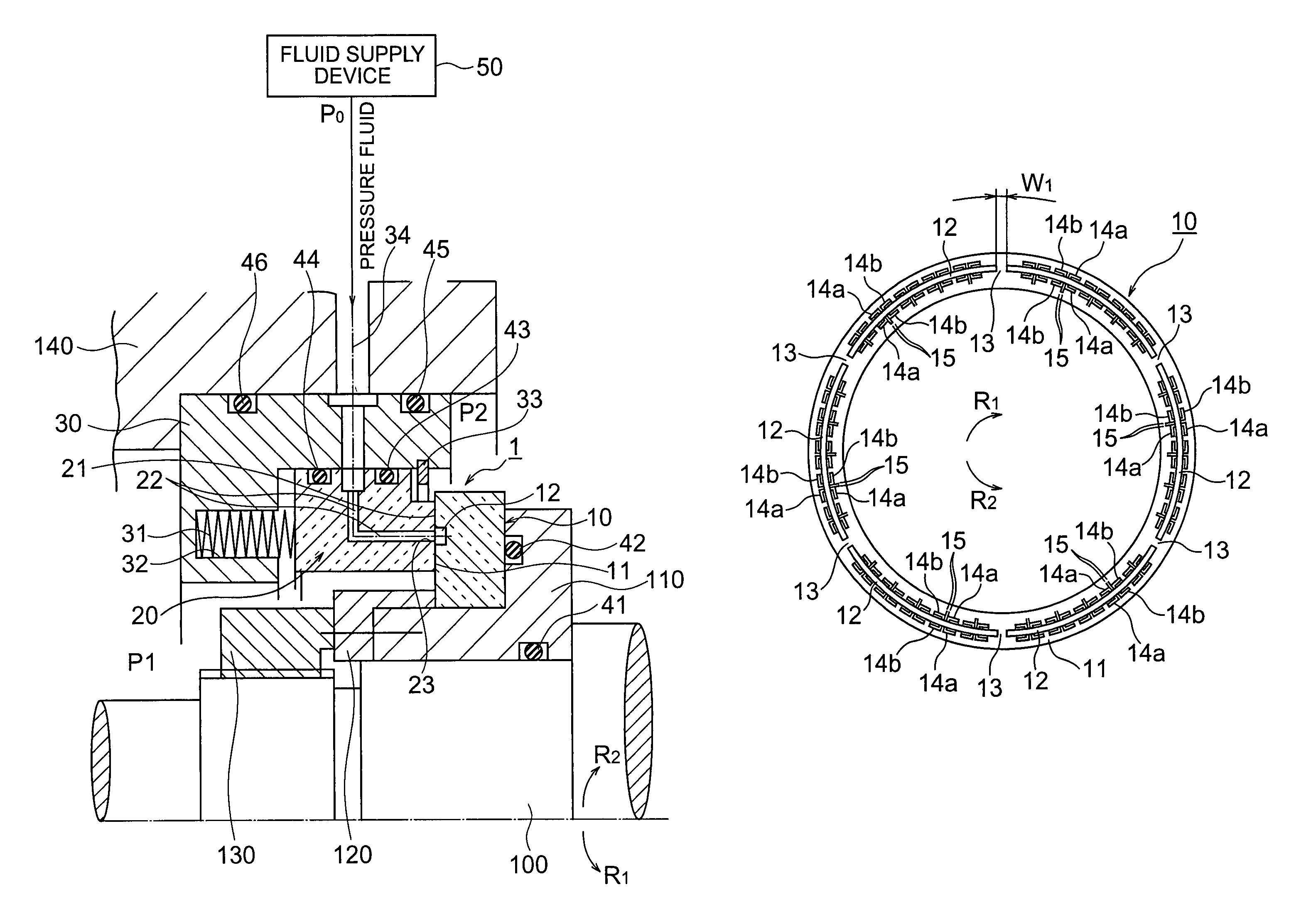
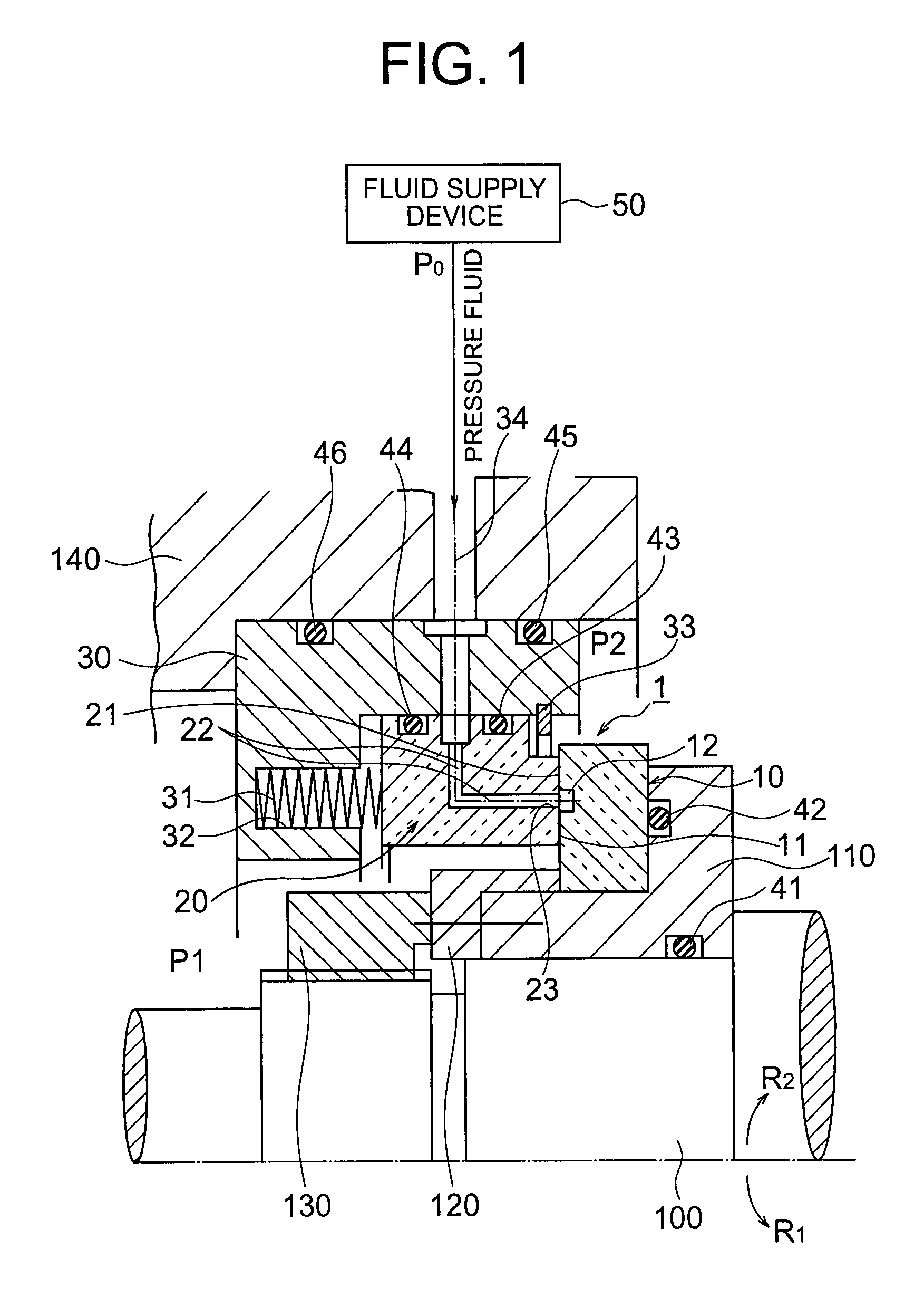
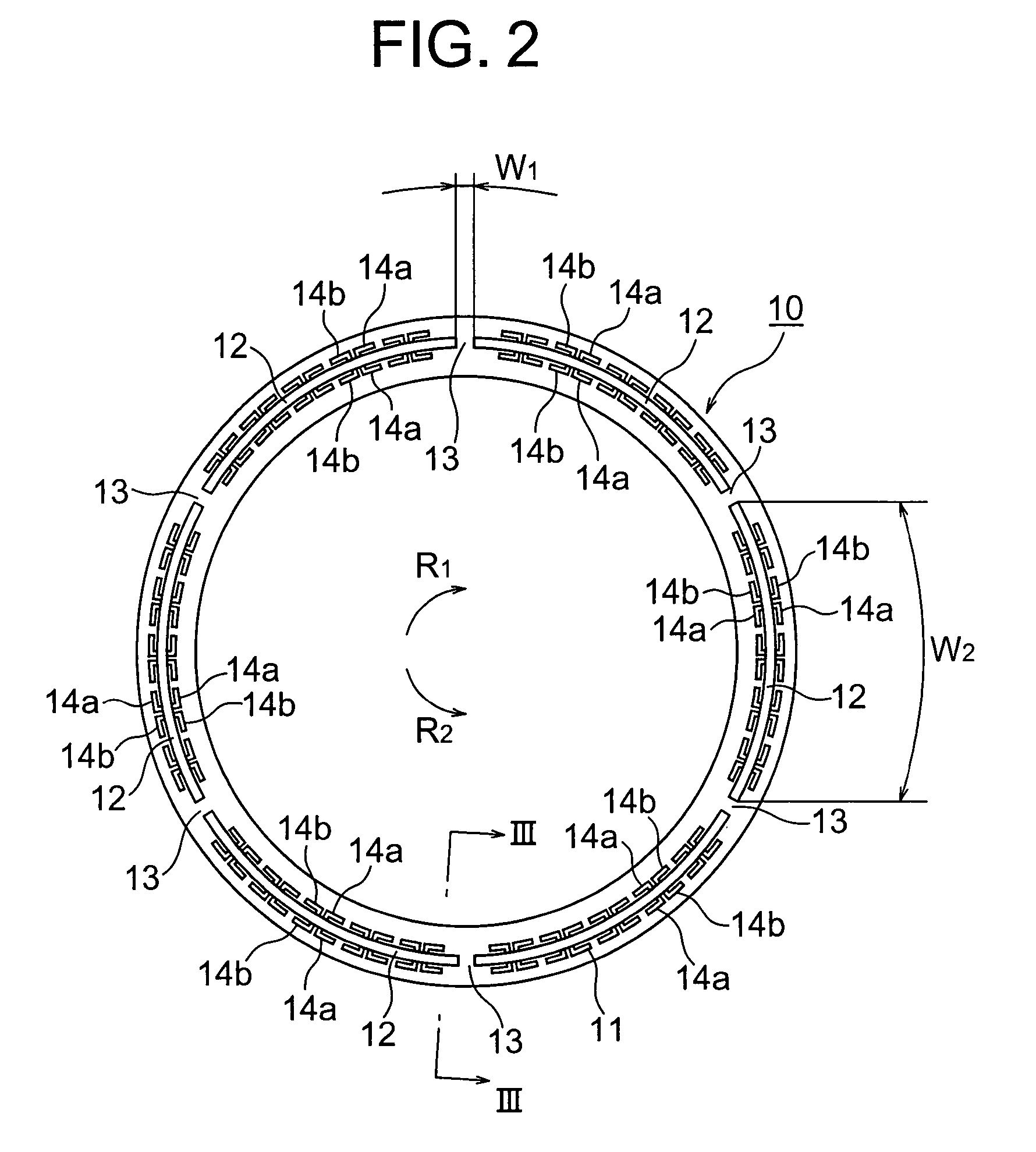
[0138]As a mechanical seal device of an example 1, a rotational seal ring having arc-shaped grooves formed thereon and a stationary seal ring having circular-shaped outlet portions formed thereon were used to produce a mechanical seal device configured as explained in the first embodiment. In the example 1, a depth t1 of the arc-shaped grooves was 1 mm, a circumferential direction length W2 of the arc-shaped grooves was 112 mm, a circumferential direction length W1 of the partition walls was 4 mm and a circumferential direction length W3 of the outlet portions was 2 mm. A production condition of the mechanical seal device produced in the example 1 is shown in Table 1.

[Table 1]

[0139]

TABLE 1Partition WallArc-shaped GrooveCutOutlet PortionDepthCDL*CDL*AmountDepthCDL*Formedt1W2W1Cut ort1−t0Formedt2W3or Not[mm][mm][mm]Not[mm]or Not[mm][mm]Example 1Yes11124No—No—2Example 2Yes11124Yes0.07No—2Example 3Yes0.051124No—Yes0.515.4ComparativeNo———No—Yes0.25112Example*CDL = Circumferential Directi...

example 2

[0142]As a mechanical seal device of an example 2, a rotational seal ring having arc-shaped grooves formed thereon and low partition walls and a stationary seal ring having arc-shaped outlet portions formed thereon were used to produce a mechanical seal device configured as explained in the seventh embodiment. In the example 2, a depth t1 of the arc-shaped grooves was 1 mm, a circumferential direction length W2 of the arc-shaped grooves was 112 mm, a circumferential direction length W1 of the partition walls was 4 mm, a cutting amount (t1−t0) at upper parts of the partition walls was 0.07 mm and a circumferential direction length W3 of the outlet portions was 2 mm. A production condition of the mechanical seal device produced in the example 2 is shown in Table 1. Vibration evaluation was made on the mechanical seal device of the example 2 under conditions of 31 patterns in the same way as in the example 1. FIG. 20 is a graph showing a result of the vibration evaluation of the mechan...

example 3

[0143]As a mechanical seal device of an example 3, a rotational seal ring having arc-shaped grooves formed thereon and a stationary seal ring having arc-shaped outlet portions formed thereon were used to produce a mechanical seal device configured as explained in the eighth embodiment. In the mechanical seal device of the example 3, a depth t1 of the arc-shaped grooves was 0.05 mm, a circumferential direction length W2 of the arc-shaped grooves was 112 mm, a circumferential direction length W1 of the partition walls was 4 mm, a depth t2 of the outlet portions was 0.5 mm and a circumferential direction length W3 of the outlet portions was 15.4 mm. A production condition of the mechanical seal device produced in the example 3 is shown in Table 1. Vibration evaluation was made on the mechanical seal device of the example 3 under conditions of 28 patterns in the same way as in the example 1. FIG. 21 is a graph showing a result of the vibration evaluation of the mechanical seal device in...


PUM


Abstract

A mechanical seal device includes a rotational seal ring connected to a rotational shaft, having a rotational seal surface and arc-shaped grooves arranged on the rotational seal surface. The grooves are sectionalized by partition walls. A stationary seal ring has a stationary seal surface facing the rotational seal surface of the rotational seal ring. A spring biases the stationary seal ring against the rotational seal ring. Outlet portions are formed on the stationary seal surface of the stationary seal ring and connect with a fluid supply path for supplying a pressure fluid. A circumferential direction length (W3) of each outlet portion is made to be ½ of a circumferential direction length (W1) of each partition wall or longer (W3≧W1 / 2); and a circumferential direction length (W3) of the outlet portions is made to be shorter than a circumferential direction length (W2) of the arc-shaped grooves (W3<W2).

Description

CROSS-REFERENCE TO RELATED APPLICATION[0001]This application is a National Stage entry of International Application No. PCT / JP2005 / 1019923, filed Oct. 28, 2005, the entire specification claims and drawings of which are incorporated herewith by reference.TECHNICAL FIELD[0002]The present invention relates to a mechanical seal device wherein incorporation of an abrasion powder to a sealed fluid is prevented by preventing wear between seal surfaces of a seal ring by suppressing vibration of the rotational seal ring and preventing contact between the seal surfaces.BACKGROUND ART[0003]A technique of the present invention is useful as a mechanical seal for sealing a fluid to be sealed in semiconductor production facilities, etc. In semiconductor production facilities, etc., when an impurity is included in a sealed fluid, it adversely affects the products. Therefore, it is necessary to prevent incorporation of an abrasion powder to the sealed fluid caused by wear of a seal ring at the time ...

Claims


Application Information

Patent Timeline
Patent Type & Authority Patents(United States)
IPC IPC(8): F16J15/40
CPCF16J15/342F16J15/3412F16J15/34H01L21/02
Inventor YANAGISAWA, TAKASHIAKIYAMA, KOJIITO, MASANOBUUCHIYAMA, MAMI
Owner EAGLE INDS
Why Eureka
Try Eureka