Card edge connector assembly

a connector and card edge technology, applied in the direction of coupling device connection, coupling device two-part connection, coupling/disengagement of coupling parts, etc., can solve the problem that the width of the electrical card cannot exceed certain limits, affect the layout of the circuit, and the performance of the electrical product is degraded, so as to avoid abrasion and breakage, increase the size of the electrical card, and increase the elasticity

Active Publication Date: 2005-03-03
MOLEX INC
View PDF1 Cites 29 Cited by
  • Summary
  • Abstract
  • Description
  • Claims
  • Application Information

AI Technical Summary

Benefits of technology

[0014] The lengths of the elastic arms of the elastic element of the fixing structure increase in such a way that the elasticity becomes greater so as to avoid abrasion and breakage for insufficient elasticity of the elastic element. The size of the electrical card can be increased and the design of the circuit board becomes more flexible in a manner that the fixing structure and the connector are formed on the circuit board separately. Operation of the electrical card is simplified, and the electrical card is easily disassembled because of the good elasticity of the elastic arms.
[0015] The present invention may also include a beveled edge and the clasp portion of the elastic arm to limit the electrical card movement in an upward and downward direction, and a protrusion of the fixing portion of the elastic element abuts against the rear rim of the electrical card to limit the electrical card movement laterally, and the limiting surfaces in the positioning slot of the elastic arm limits the lateral movement of the electrical card. This structure increases the shock resistance of the fixing structure and ensures the electrical contact between the electrical card and the connector.
[0016] The fixing structure may further comprise a stop plate, wherein a rear stop piece of the stop plate and the elastic arm define a gap to provide a retracting distance for the elastic arm so as to prevent the elastic arm from breaking from being overextended when it is pulled backwardly.

Problems solved by technology

If the connection is not stable, the signals may become intermittent, thereby degrading the performance of the electrical product.
However, when the connector is first fixed on the circuit board, the predetermined space for the connector of the circuit board will affect the circuit layout.
Second, when the electrical card plugs into the insertion slot, the distance between the two side frames limits the width of the electrical card so that the width of the electrical card cannot have variance beyond certain limits.
Furthermore, the two side frames are made of plastic so that it lacks sufficient rigidity.
As such, the two side frames may deflect, distort or even break because of the extension of the two side frames during the insertion and removal of the electrical card resulting in loss of the fixing function of the side frames.
The clasp element of the fixing structure is made of plastic, and the length of the buckling portion is small due to the thin nature of the notebook computer, so that the elasticity of the buckling portion is insufficient.
As can be seen from the above, the conventional card edge connector assembly has some inconvenience and problems in use, and the above-mentioned fixing structure of the electrical card also needs to be improved.

Method used


Image

  • Card edge connector assembly
  • Card edge connector assembly
  • Card edge connector assembly

Examples


first embodiment

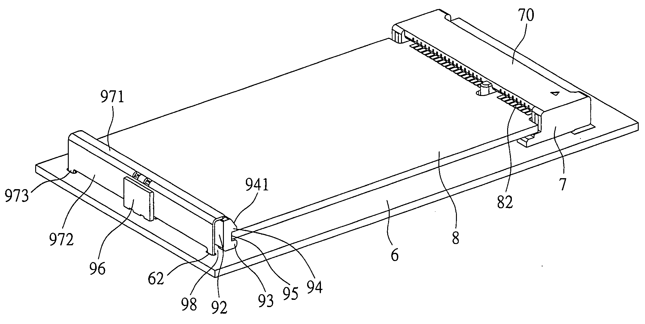
[0035] In the present invention, the fixing portion 91 and the elastic arm 92 of the elastic element 90 have a height dimension the same as the clasp portion 94 of the free end. The top stop piece 971 of the stop plate 97 is positioned from the top surfaces of the fixing portion 91 and the elastic arm 92 to the top surface of the clasp portion 94.

second embodiment

[0036] Referring to FIGS. 7-8, in the present invention, the fixing portion 91 and the elastic arm 92 are lower than the clasp portion 94 of the free end of the elastic arm 92. The top stop piece 971 of the stop plate 97 is positioned on the top surfaces of the fixing portion 91 and the elastic arm 92 which are close to the positioning slot 95 and between the two clasp portion 94. This can save space and material cost for the low height of the top stop piece positioned.


PUM


Abstract

A card edge connector assembly includes a circuit board, a connector, an electrical card and a fixing structure. The connector is formed on the circuit board, the front rim of the electrical card is inserted into the insertion slot of the connector. The fixing structure has an elastic element having a fixing portion positioned on the circuit board. Two relating opposing sides of the fixing portion extends two elastic arms whose free ends form a beveled edge and a clasp portion, and define positioning slots on the rear rim of the electrical card. The length of the elastic arm increases in such a way that the elasticity of the elastic arm becomes greater so as to prevent the elastic arm abrading and breaking to ensure the positioning function and enhance the shock-resistance.

Description

FIELD OF THE INVENTION [0001] The present invention relates to a card edge connector assembly, and more particularly to a card edge connector wherein a fixing structure is separate from a connector. BACKGROUND OF THE INVENTION [0002] Electrical products include various types of electrical connectors for receiving electrical cards. In order to keep the electrical connection therebetween, the connector and the electrical card must be connected stably. If the connection is not stable, the signals may become intermittent, thereby degrading the performance of the electrical product. [0003] Referring to FIG. 1, a conventional card connector assembly comprises a circuit board 2a, a connector 1a and an electrical card (not shown). The connector 1a is formed on the circuit board 2a and comprises an insulative housing 10a, a plurality of terminals 11a and two metallic rods 12a. The insulative housing 10a has a base portion 13a, and two side frames 14a which has two insertion slots 15a on two ...

Claims


Application Information

Patent Timeline
Patent Type & Authority Applications(United States)
IPC IPC(8): H01R12/18H01R13/62H01R13/639
CPCH01R12/721H01R12/52
Inventor HO, YI-TSETOJO, KATSUTOSHI
Owner MOLEX INC
Why Eureka
Try Eureka