Backlight module and display device

A technology of backlight module and light source, which is applied in the direction of lighting devices, components of lighting devices, optics, etc., and can solve the problems that the optical film 4 is prone to collapse, affects the product quality of the display device, and the optical film cannot move relative to each other. Achieve the effects of preventing relative movement, avoiding bright edges, and reducing gaps

Active Publication Date: 2014-01-01
HISENSE VISUAL TECH CO LTD
View PDF8 Cites 27 Cited by
  • Summary
  • Abstract
  • Description
  • Claims
  • Application Information

AI Technical Summary

Problems solved by technology

The disadvantage of such a backlight module is that since the light guide plate 2 is tightly pressed by the plastic frame 3, and the optical film 4 and the plastic frame 3 are fixed by means of limiting or fixing columns, such a The fixing method is difficult to tightly fix the optical film 4 and the plastic frame 3, so that the optical film 4 moves within the scope of the plastic frame 3. In addition, due to the softness of the optical film 4 itself, the optical film 4 itself Under the action of gravity or other external forces, the optical film 4 is prone to collapse and contact with the surface of the light guide plate 2, which will cause relative movement between the optical film 4 and the light guide plate 2
and figure 1 The difference of the shown backlight module is that the optical film 4 is directly arranged on the light-emitting side surface of the light guide plate 2, and the surroundings of the optical film 4 are tightly pressed and fixed by the plastic frame 3, so that the optical film 4 and the The light guide plate 2 cannot move relative to each other even under severe vibration
The disadvantage of such a backlight module is that the light emitted by the light source 1 should usually enter the light guide plate 2 directly, but in the actual use process, there is usually a certain assembly gap between the plastic frame 3 and the optical film 4 , it is difficult to completely compress, so the light guide plate 2 is prone to warping, which will make it difficult for the light source 1 to be completely aligned with the light guide plate 2, so that part of the light (such as figure 2 (indicated by the middle arrow) is emitted from the edge of the light guide plate 2, and this part of the light will directly enter the optical film 4. Since the optical film 4 has light refraction characteristics, the incident light from the bottom of the optical film 4 can be well obtained Diffusion and homogenization, and the light incident from the side of the optical film 4 will converge within a certain range, thereby generating strong convergent light in the edge area A covered by the plastic frame 3, even if the light source 1 can be integrated with the light guide plate 2 are completely aligned, there will still be a certain intensity of concentrated light in this area, resulting in bright edges that can be observed by the human eye at the edge of the backlight module, especially for backlight modules with narrow borders, due to the width of the plastic frame 3 limited, this bright edge phenomenon will be more obvious, seriously affecting the quality of display device products

Method used


Image

  • Backlight module and display device
  • Backlight module and display device
  • Backlight module and display device

Examples


Embodiment Construction

[0034] The following will clearly and completely describe the technical solutions in the embodiments of the present invention with reference to the accompanying drawings in the embodiments of the present invention. Obviously, the described embodiments are only some, not all, embodiments of the present invention. All other embodiments obtained by persons of ordinary skill in the art based on the embodiments of the present invention belong to the protection scope of the present invention.

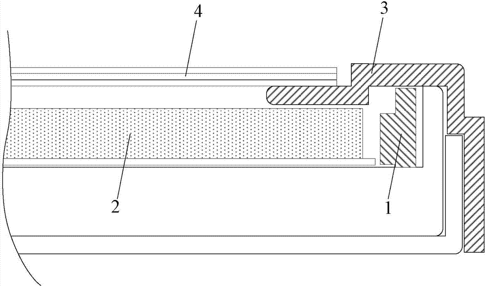
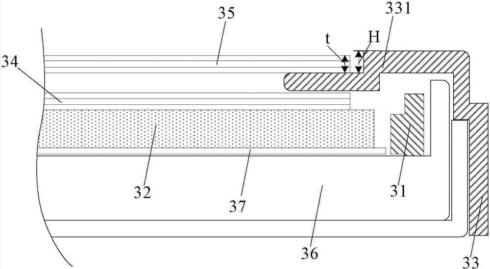
[0035] The backlight module provided by the embodiment of the present invention, such as image 3 As shown, it includes: a light source 31, a light guide plate 32 and a plastic frame 33, and the backlight module also includes:

[0036] The first optical film layer 34 disposed on the light-emitting side surface of the light guide plate 32 and the second optical film layer 35 disposed on the light-emitting side of the first optical film layer 34 .

[0037] Wherein, the plastic frame 33 has a p...


PUM


Abstract

The embodiment of the invention discloses a backlight module and a display device, and relates to the field of display technologies. The backlight module comprises a light source, a light guide plate and a rubber frame used for packaging the backlight module. The backlight module further comprises a first optical film layer and a second optical film layer, wherein the first optical film layer is arranged on the surface of a light-emitting side of the light guide plate, and the second optical film layer is arranged on a light-emitting side of the first optical film layer. The rubber frame is provided with a protruded portion, part of the protruded portion is located between the first optical film layer and the second optical film layer to separate the first optical film layer from the second optical film layer. Thus, the backlight module can prevent relative movement between optical films and the light guide plate, and bright borders on edges of the backlight module can be avoided.

Description

technical field [0001] The invention relates to the field of display technology, in particular to a backlight module and a display device. Background technique [0002] With the continuous improvement of LCD (Liquid Crystal Display, liquid crystal display) display technology, LCD has been widely used in various display fields, and people's requirements for LCD quality are also constantly improving. [0003] Since the LCD itself does not emit light, the quality of the backlight module of the LCD is particularly important, and the quality of the backlight module will directly affect the display effect of the display device. Backlight modules can be divided into two types: direct-type and side-type according to the way the light enters the display panel. Compared with the direct-type backlight module, the side-type backlight module uses side-side light input, which can effectively reduce the backlight. The number of lamps used can reduce energy consumption and save production ...

Claims


Application Information

Patent Timeline
Patent Type & Authority Applications(China)
IPC IPC(8): F21S2/00F21V17/00G02F1/13357
Inventor 李响宋志成
Owner HISENSE VISUAL TECH CO LTD
Why Eureka
Try Eureka