Method and Apparatus for Visualizing the Position of an Operating Head Relative to a Workpiece

a technology of operating head and workpiece, which is applied in the field of visualizing the position of the operating head relative to the workpiece, can solve the problems of difficult to follow the quilting pattern on the pantograph and observe the sewing quality, and the need to acquire and retain many scrolls. large and difficult to handl

Active Publication Date: 2013-07-25
ABM INT INC +1
View PDF19 Cites 25 Cited by
  • Summary
  • Abstract
  • Description
  • Claims
  • Application Information

AI Technical Summary

Benefits of technology

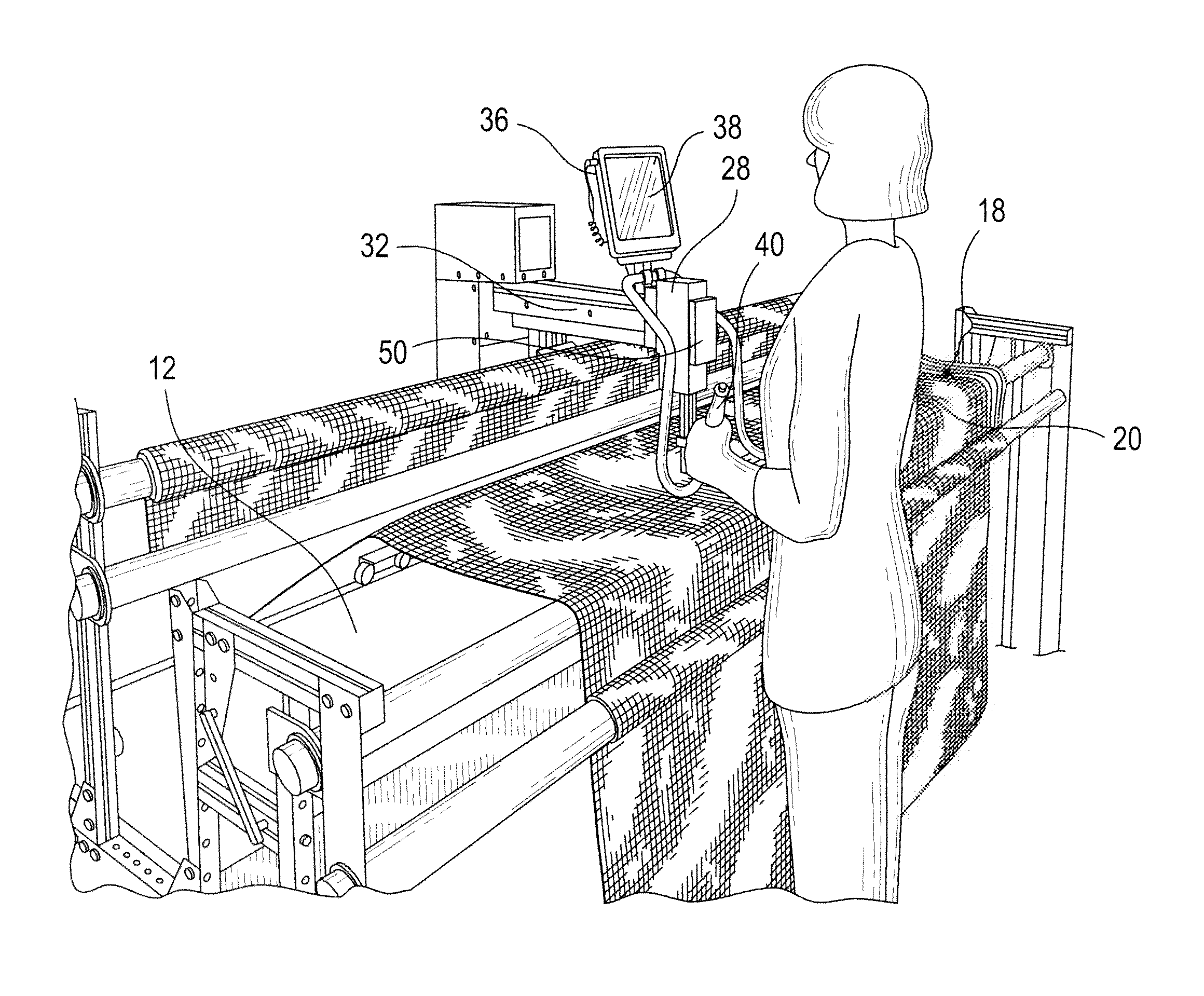
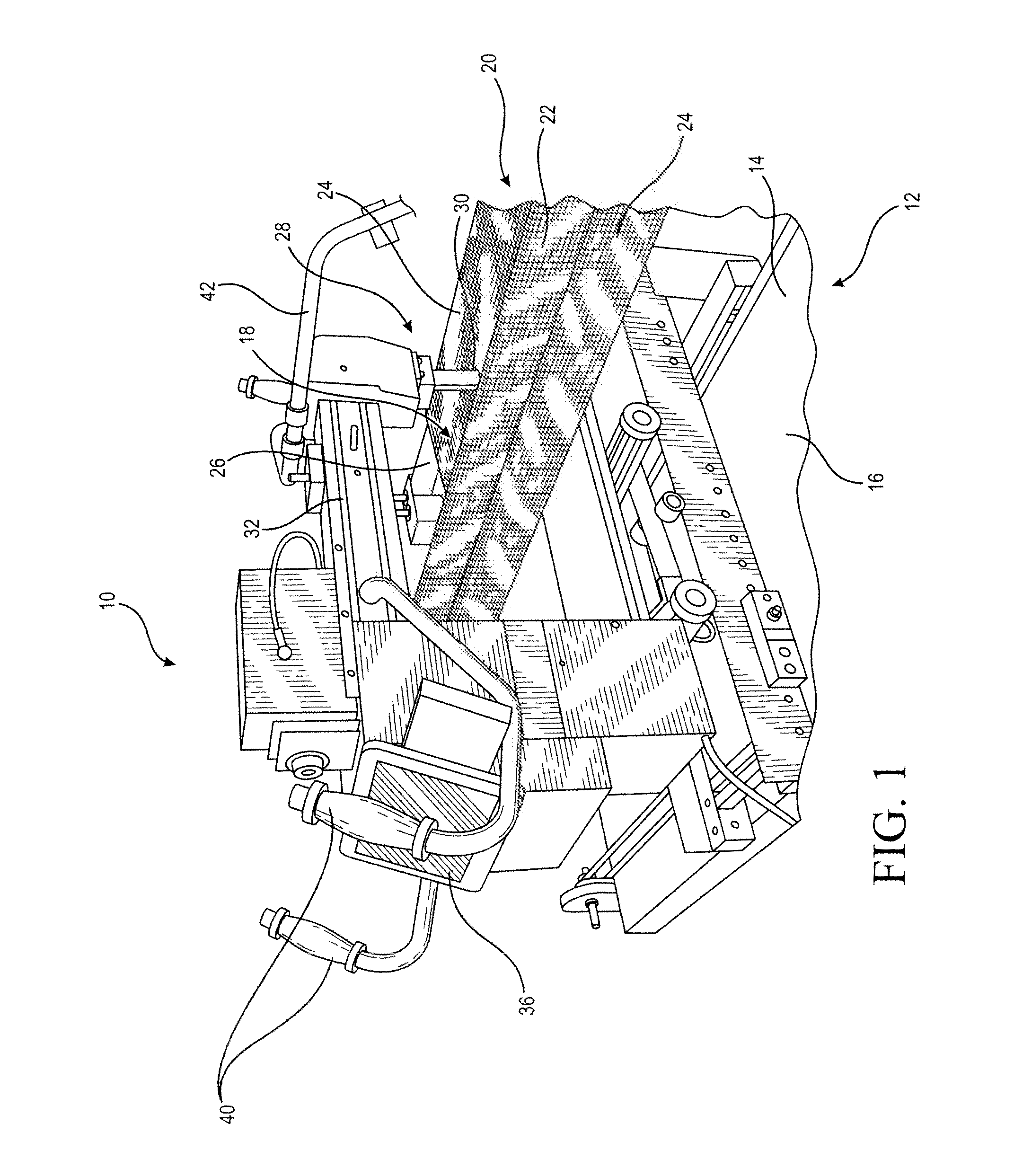
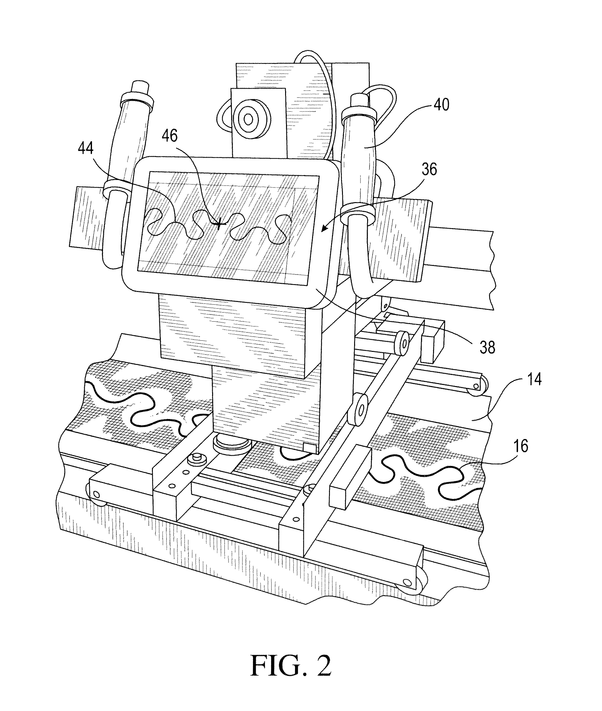
[0014]The present disclosure provides a method of stitching a workpiece where a user moves a display to move an indicator relative to a displayed pattern, and a sewing head relative to the workpiece. The present disclosure also provides a method of stitching a workpiece where a user moves a display to move a displayed pattern relative to a fixed position of an indicator wherein the indicator corresponds to a location of a sewing head. Further, the present disclosure provides a method of stitching a workpiece where a user moves a display to move an indicator and a disp

Problems solved by technology

A problem with these machines, however, is that they are large and difficult to handle.
Further, because the user is located farther away from the needle when using a paper pantograph, or scroll, as a guide, it is difficult to follow a quilting pattern on a pantograph and observe the sewing quality.
In addition, the need to acquire and retain numerous scrolls is expensive and requires significant storage space.
Despite the machine providing a more efficient quilting experience, many users are still not satisfied with the quality of the stitch

Method used


Image

  • Method and Apparatus for Visualizing the Position of an Operating Head Relative to a Workpiece
  • Method and Apparatus for Visualizing the Position of an Operating Head Relative to a Workpiece
  • Method and Apparatus for Visualizing the Position of an Operating Head Relative to a Workpiece

Examples


Embodiment Construction

[0027]At the outset, it should be appreciated that the use of the same reference number throughout the several figures designates a like or similar element.

[0028]For purposes of the present disclosure and appended claims, the conjunction “or” is to be construed inclusively (e.g., “a bear or a pig” would be interpreted as “a bear, or a pig, or both”; e.g., “a bear, a pig, or a mouse” would be interpreted as “a bear, or a pig, or a mouse, or any two, or all three”), unless: i) it is explicitly stated otherwise, e.g., by use of “either . . . or”, “only one of . . . ”, or similar language; or ii) two or more of the listed alternatives are mutually exclusive within the particular context, in which case “or” would encompass only those combinations involving non-mutually-exclusive alternatives.

[0029]For purposes of the present disclosure or appended claims, the words “comprise”, comprising”, “have”, “having”, “include”, “including”, and so on shall be construed as being open-ended, e.g., “...


PUM


Abstract

A method and apparatus for stitching a workpiece, such as a quilt, is disclosed. The method comprises displaying a predetermined pattern on a display and manipulating the predetermined pattern on the display. The display includes an indicator corresponding to a position of a sewing head relative to the workpiece. The method further includes moving a control handle operably connected to the sewing head to move the indicator relative to the pattern on the display and move the sewing head relative to the workpiece. Devices to practice the method include sewing machines having a sewing head moveable relative to a workpiece and a control handle operably connected to the sewing head to move the sewing head relative to the workpiece, wherein the display showing a pattern to be sewn is mounted relative to the control handle for movement with the control handle.

Description

CROSS-REFERENCE TO RELATED APPLICATIONS[0001]None.STATEMENT REGARDING FEDERALLY SPONSORED RESEARCH OR DEVELOPMENT[0002]None.REFERENCE TO A “SEQUENCE LISTING”[0003]None.BACKGROUND OF THE INVENTION[0004]1. Technical Field[0005]The present invention relates to a system for visualizing a position of an operating head relative to a workpiece. In one configuration, the present system assists a user in making a pattern on a workpiece using a free-motion machine. A further configuration relates to sewing machines for quilting and more specifically to a method and apparatus for sewing quilting patterns onto a workpiece by displaying a pattern and an indicator on a display apparatus, the indicator corresponding to a position of a sewing head relative to the workpiece, and moving the display apparatus to move the indicator relative to the displayed pattern and move the sewing head relative to the workpiece.[0006]2. Description of Related Art[0007]A quilt is a coverlet that typically has three ...

Claims


Application Information

Patent Timeline
IPC IPC(8): D05B19/12
CPCD05B19/12D05B11/00D05B19/06D05B19/10
Inventor SCHNAUFER, WILLIAM E.SCHWARZBERGER, NEAL A.
Owner ABM INT INC
Why Eureka
Try Eureka