
Quick Take-Down Barrel System and Method for Modular Rifle

a modular rifle and barrel system technology, applied in the field of modular rifle barrel system and modular rifle method, can solve the problems of inability to quickly and easily remove the barrel, change the barrel, or disassemble the rifle system, and the barrel cannot be quickly and easily stored in a disassembled state, so as to achieve the effect of simple and rapid change of the barrel assembly

Active Publication Date: 2013-08-15
THE OTIS PATENT TRUST
View PDF12 Cites 56 Cited by
  • Summary
  • Abstract
  • Description
  • Claims
  • Application Information

AI Technical Summary

Benefits of technology

The new system and method described in this patent allows for quick and easy assembly and disassembly of M-16 / AR-15 modular rifle systems. It does not require specialized tools and can be done in the field without a bench vise. The barrel assembly is easily inserted and tightened by hand force only. The system also includes a mechanism to prevent the barrel nut connector sleeve from rotating during firing. This mechanism attaches a hand guard portion to the barrel nut connector sleeve to keep it from rotating. Overall, this system provides a compact and efficient way to assemble, disassemble, and store these modular rifle systems.

Problems solved by technology

Consequently, the barrel cannot be quickly or easily removed, changed, or assembled in the field under combat conditions or exigent circumstances, and the rifle system cannot be quickly and easily stored in a disassembled state.

Method used


Image

  • Quick Take-Down Barrel System and Method for Modular Rifle
  • Quick Take-Down Barrel System and Method for Modular Rifle
  • Quick Take-Down Barrel System and Method for Modular Rifle

Examples


Embodiment Construction

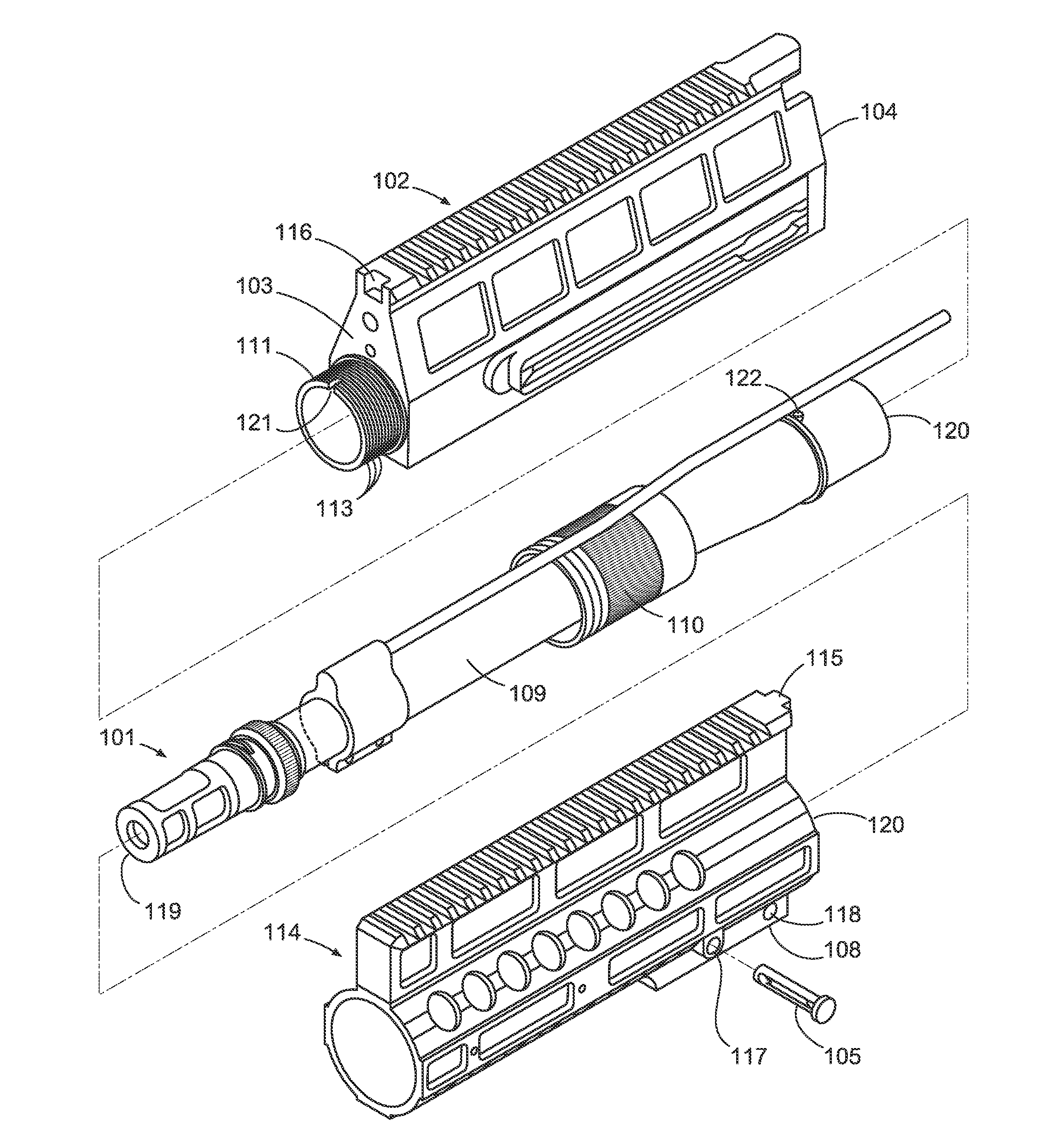
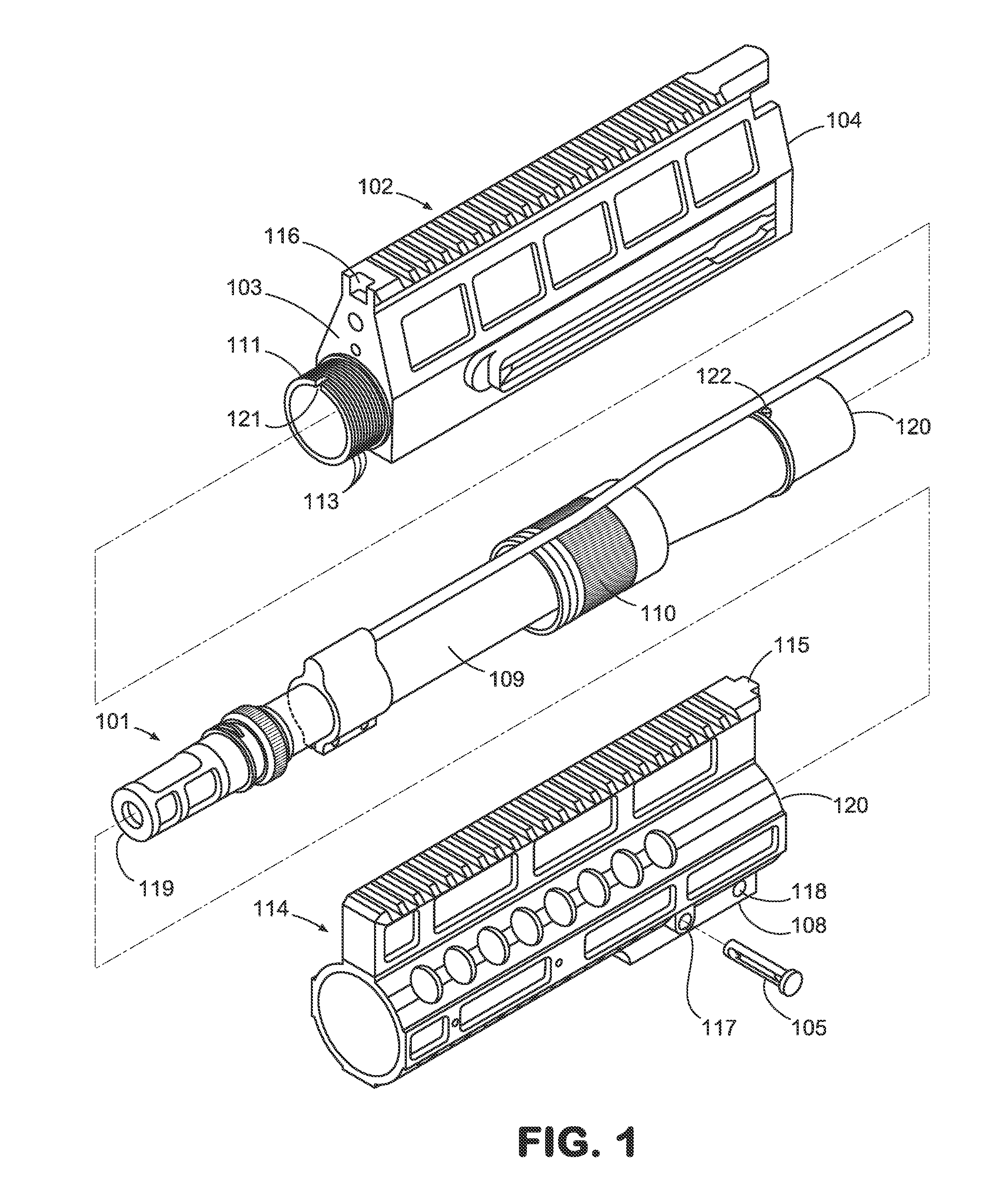
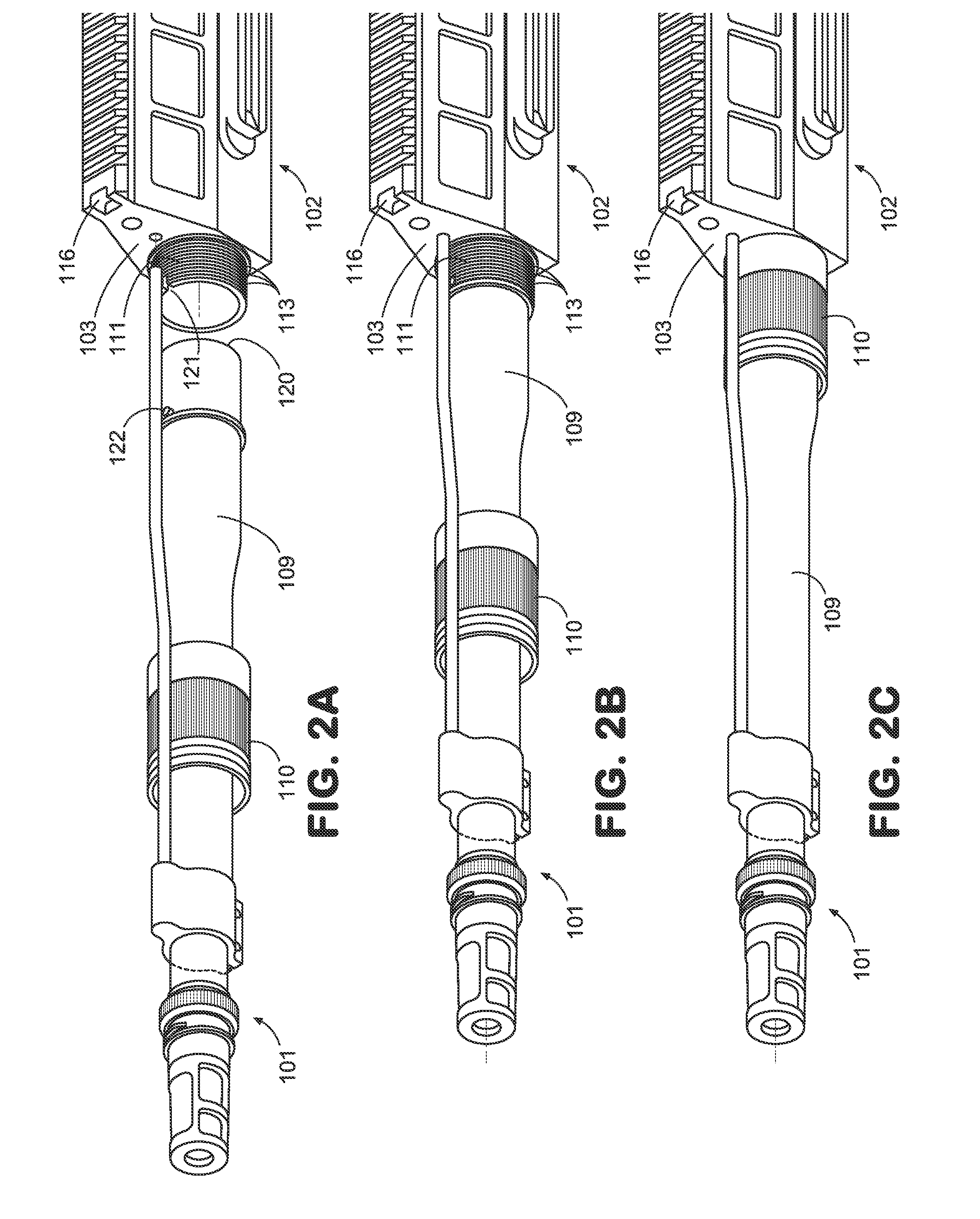
[0013]Disclosed below are embodiments of a quick take-down barrel system and methods for a modular rifle system. FIG. 1 is a perspective view of a fore 114 and aft 102 portions of an upper receiver assembly and a barrel assembly 101 in accordance with one exemplary embodiment of the present invention. Barrel assembly 101 is affixed to the front face 103 of aft portion 102 of upper receiver assembly by means of a threaded barrel nut connector sleeve 110. Aft portion 102 of upper receiver assembly and barrel assembly 101 are coupled to a fore portion 114 of upper receiver assembly, comprising a hand guard, by means of a takedown pin 105, an alignment tab 115, and a slotted screw clamp 108.

[0014]With reference to FIG. 1, aft portion 102 of upper receiver assembly is comprised of a forward face 103 and a rearward face 104. Forward face 103 of aft portion 102 of upper receiver assembly contains a nipple 111 with circumferential machined threads 113 around its outer diameter and an alignm...


PUM

PropertyMeasurementUnit
pressureaaaaaaaaaa
outer diameteraaaaaaaaaa
diameteraaaaaaaaaa

Abstract

In embodiments, a modular rifle includes a lower receiver assembly, an upper receiver assembly housing a barrel, and a coupling mechanism. Upper receiver assembly has two portions, an aft portion and fore portion, commonly comprising a hand guard. The barrel is releasably attached to the upper receiver first portion by a hand-tightenable barrel nut sleeve connector. Upper receiver second portion is both releasably attached to the barrel nut connector sleeve and to the upper receiver first portion to prevent the barrel nut connector sleeve from rotating during firing of the rifle and to keep the second portion from detaching during firing of the rifle. Attachment of upper receiver second portion to the barrel nut connector sleeve is accomplished by a removable take-down pin and common screw clamp, which secure the barrel nut connector sleeve. Upper receiver first and second portions are connected by an attachment tab and receptacle.

Description

BACKGROUND OF THE INVENTION[0001]A rifle is a type of weapon that fires rounds. Typically, the rifle includes a trigger, a hammer, and a barrel. The round is positioned in the barrel, and, when the trigger is pulled, the hammer fires the round through the barrel. A modular rifle typically includes a lower receiver assembly, an upper receiver assembly housing the barrel, and a coupling mechanism. The M-16 style rifle is a type of modular rifle system commonly used by military and police forces that features a gas-operated bolt and bolt carrier system, as disclosed, for example, in U.S. Pat. No. 2,951,424, issued to Eugene M. Stoner on Sep. 6, 1960 (incorporated herein by reference in its entirety). The AR-15 style rifle is a similarly designed modular rifle system commonly sold and used in civilian applications.[0002]For most M-16 / AR-15 style rifle systems, the barrel is assembled by connecting the barrel to the upper receiver utilizing a barrel nut. The barrel nut must be appropriat...

Claims


Application Information

Patent Timeline
Patent Type & Authority Applications(United States)
IPC IPC(8): F41A11/02B23P11/00F41A21/00
CPCF41A3/66F41A11/02Y10T29/49822F41C23/16Y10T29/49963F41A21/482
Inventor PATEL, SWETAL K.
Owner THE OTIS PATENT TRUST
Learn More