Reducing error contributions to gyroscopic measurements

a technology of gyroscope and error contribution, applied in the field of reducing error contribution to gyroscopic measurements, can solve the problem that the process takes considerably longer to implement without the facility to index the gyroscope, and achieve the effect of reducing the contribution of error to gyroscopic measurements

Inactive Publication Date: 2013-08-15
GYRODATA
View PDF5 Cites 16 Cited by
  • Summary
  • Abstract
  • Description
  • Claims
  • Application Information

AI Technical Summary

Benefits of technology

[0009]In certain embodiments, a method of reducing error contributions to gyroscopic measurements is provided. The method comprises receiving a plurality of signals indicative of at least one component of the Earth's rotation substantially perpendicular to a portion of a wellbore and a component of the Earth's rotation substantially parallel to the portion of the wellbore. The plurality of signals is generated by one or more gyroscopic sensors within the portion of the wellbore. The method further comprises calculating, using the plurality of signals and using one or more signals indicative of the Earth's rotation rate and one or more signals indicative of the latitude of the one or more gyroscopic sensors within the portion of the wellbore, a mass unbalance offset for the one or more gyroscopic sensors.

Problems solved by technology

While azimuth can be determined using a strapdown system, the process takes considerably longer to implement without the facility to index the gyro.
However, the mechanical complexity and consequent size of such a system preclude it as a viable option for down-hole application.

Method used


Image

  • Reducing error contributions to gyroscopic measurements
  • Reducing error contributions to gyroscopic measurements
  • Reducing error contributions to gyroscopic measurements

Examples


Embodiment Construction

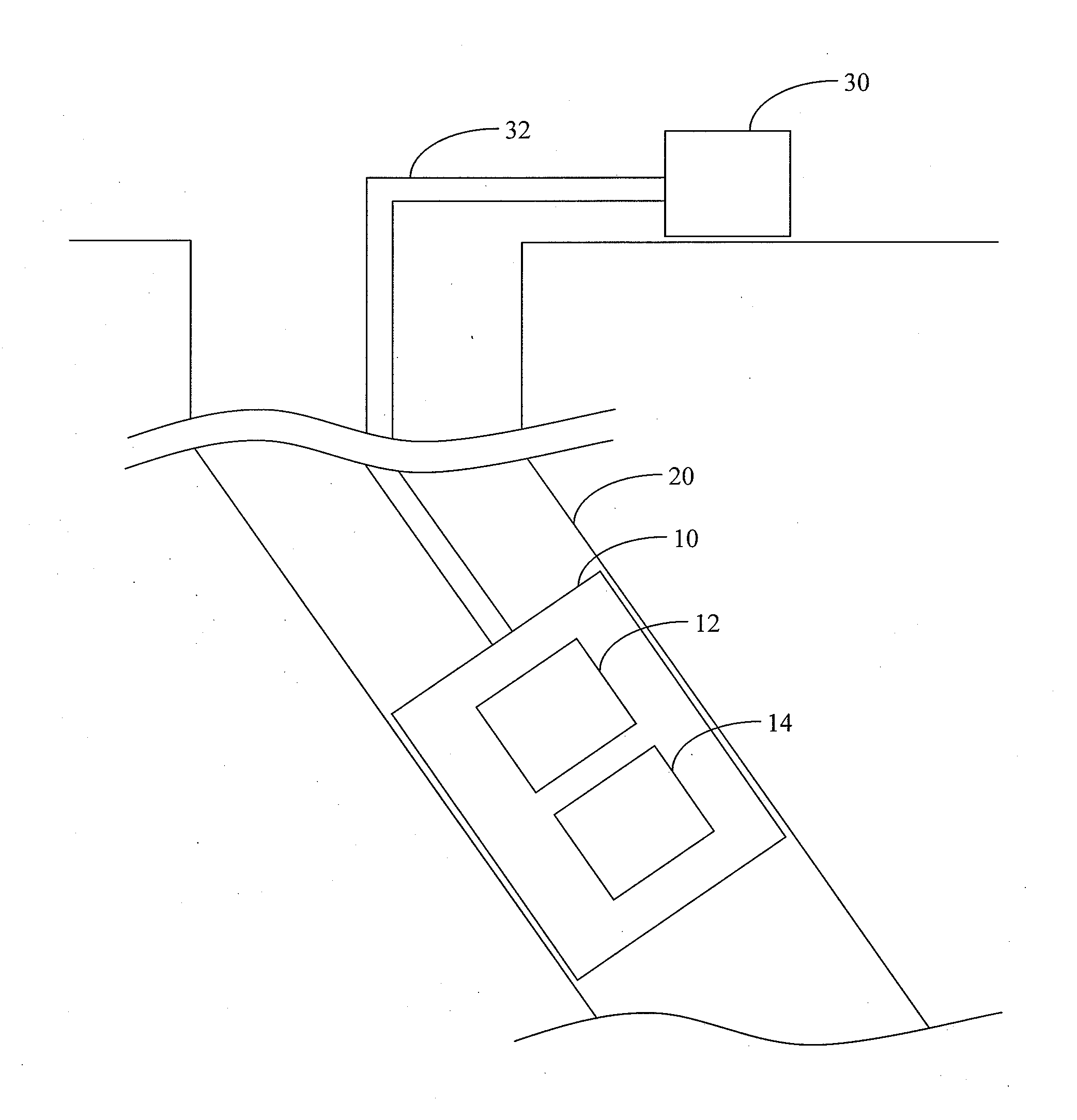
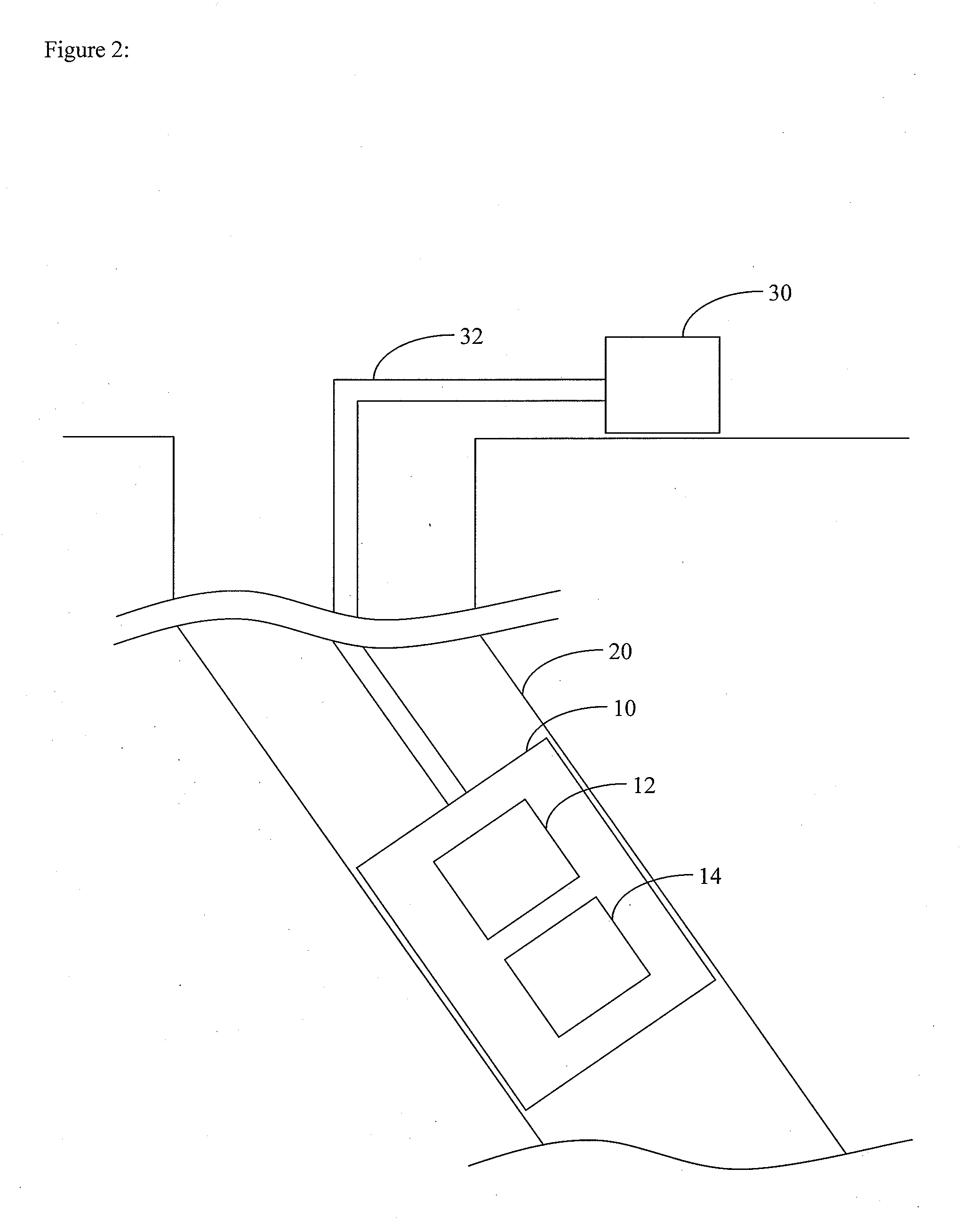
[0032]There is an increasing demand for high accuracy surveys of highly deviated and extended reach wellbores. For example, modern survey systems may operate at any attitude, e.g., at 90 degrees inclination and beyond in horizontal extended reach wells, and high accuracy surveys in such wellbores are desirable. As used herein, the terms “surveys,”“survey systems,” and “survey tools” have their broadest reasonable meaning to persons of ordinary skill in the art, which includes, but is not limited to, surveys, systems and tools for such surveys, performed subsequent to drilling of the surveyed portion of the wellbore, as well as surveys, systems and tools for such surveys, performed concurrently with the drilling of the surveyed portion of the wellbore (e.g., by directional drilling systems and tools).

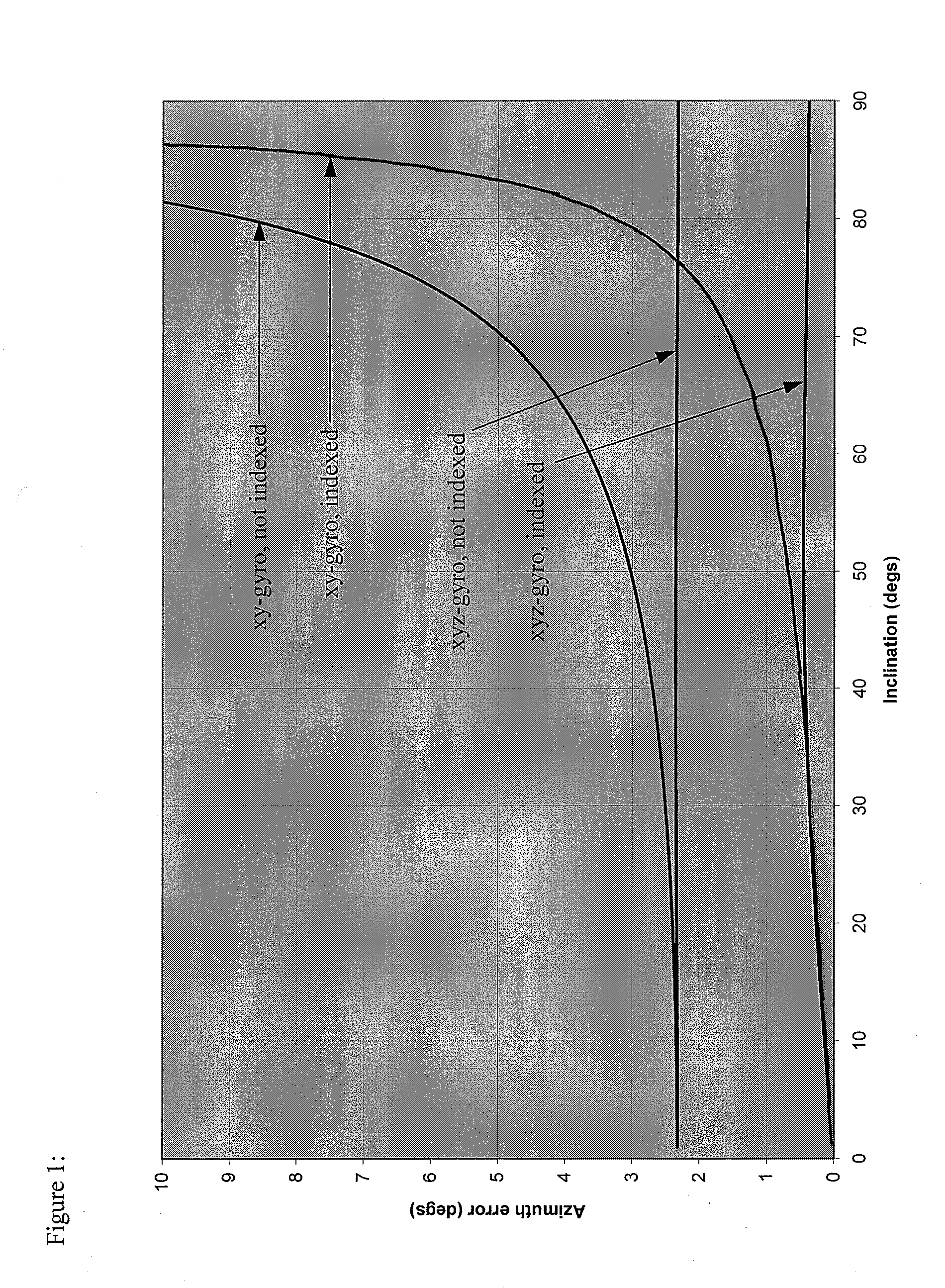
[0033]While the two-axis strapdown system outlined above provides accurate estimates of wellbore azimuth in a near vertical well, this accuracy degrades as inclination increases, with th...


PUM


Abstract

A method and system for reducing error contributions to gyroscopic measurements is provided. The method includes receiving a plurality of signals indicative of at least one component of the Earth's rotation substantially perpendicular to a portion of a wellbore and a component of the Earth's rotation substantially parallel to the portion of the wellbore. The plurality of signals is generated by one or more gyroscopic sensors within the portion of the wellbore. The method further includes calculating, using the plurality of signals and using one or more signals indicative of the Earth's rotation rate and one or more signals indicative of the latitude of the one or more gyroscopic sensors within the portion of the wellbore, a mass unbalance offset for the one or more gyroscopic sensors.

Description

CROSS-REFERENCE TO RELATED APPLICATIONS[0001]This application is a continuation-in-part of U.S. patent application Ser. No. 13 / 243,989, filed on Sep. 23, 2011 and incorporated in its entirety by reference herein, which is a continuation of U.S. patent application Ser. No. 12 / 363,465, filed Jan. 30, 2009 and incorporated in its entirety by reference herein, now issued as U.S. Pat. No. 8,065,087.BACKGROUND[0002]1. Field[0003]The present application relates generally to systems and method for reducing error contributions to gyroscopic measurements from a wellbore survey system and / or determining the position or orientation of the survey system relative to the Earth.[0004]2. Description of the Related Art[0005]Many wellbore gyroscopic survey systems that are currently in service are based on angular rate measurements taken about two axes only, denoted the x and y axes, that are both substantially perpendicular to the direction along the wellbore (referred to as the “along-hole axis”) an...

Claims


Application Information

Patent Timeline
Patent Type & Authority Applications(United States)
IPC IPC(8): G01P21/00
CPCG01P21/00E21B47/022
Inventor WESTON, JOHN LIONELLEDROZ, ADRIAN GUILLERMOEKSETH, ROGERUTTECHT, GARY WILLIAM
Owner GYRODATA
Why Eureka
Try Eureka