Reducing error contributions to gyroscopic measurements from a wellbore survey system

a wellbore survey and gyroscopic measurement technology, applied in the field of reducing error contributions to gyroscopic measurements from a wellbore survey system, can solve the problem that the process takes considerably longer to implement without the facility to index the gyro, and achieve the effect of reducing error contributions, reducing error contributions, and reducing errors

Active Publication Date: 2010-08-05
GYRODATA
View PDF85 Cites 34 Cited by
  • Summary
  • Abstract
  • Description
  • Claims
  • Application Information

AI Technical Summary

Benefits of technology

[0008]In certain embodiments, a method reduces error contributions to gyroscopic measurements. The method comprises providing a survey system within a portion of a wellbore. The survey system comprises a first gyroscopic sensor adapted to generate measurement signals indicative of at least one component of the Earth's rotation substantially perpendicular to the portion of the wellbore. The survey system further comprises a second gyroscopic sensor adapted to generate measurement signals indicative of a component of the Earth's rotation substantially parallel to the portion of the wellbore. The method further comprises generating a first measurement signal indicative of the at least one component of the Earth's rotation substantially perpendicular to the portion of the wellbore using the first gyroscopic sensor while the first gyroscopic sensor is in a first orientation relative to the wellbore. The method further comprises generating a second measurement signal indicative of the at least one component of the Earth's rotation substantially perpendicular to the portion of the wellbore using the first gyroscopic sensor while the first gyroscopic sensor is in a second orientation relative to the wellbore. The second orientation is different from the first orientation. The method further comprises generating a third measurement signal indicative of the component of the Earth's rotation substantially parallel to the portion of the wellbore using the second gyroscopic sensor while the second gyroscopic sensor is in a first orientation relative to the wellbore. The method further comprises generating a fourth measurement signal indicative of the component of the Earth's rotation substantially parallel to the portion of the wellbore using the second gyroscopic sensor while the second gyroscopic sensor is in a second orientation relative to the wellbore. The second orientation is different from the first orientation. The method further comprises calculating information regarding at least one error contribution to measurement signals from the survey system using the first measurement signal, the second measurement signal, the third measurement signal, and the fourth measurement signal. The at least one error contribution comprises at least one of a mass unbalance offset error and a quadrature bias error of at least one of the first gyroscopic sensor and the second gyroscopic sensor.
[0009]In certain embodiments, a method reduces error contributions to gyroscopic measurements. The method comprises providing a survey system within a portion of a wellbore. The survey system comprises a first gyroscopic sensor adapted to be indexed and to generate measurement signals indicative of at least one component of the Earth's rotation substantially perpendicular to the portion of the wellbore. The survey system further comprises a second gyroscopic sensor adapted to be indexed and to generate measurement signals indicative of a component of the Earth's rotation substantially parallel to the portion of the wellbore. The method further comprises using the first gyroscopic sensor to generate at least one first measurement signal indicative of the at least one component of the Earth's rotation substantially perpendicular to the portion of the wellbore. The method further comprises indexing the first gyroscopic sensor. The method further comprises using the first gyroscopic sensor to generate at least one second measurement signal indicative of the at least one component of the Earth's rotation substantially perpendicular to the portion of the wellbore. The method further comprises using the second gyroscopic sensor to generate at least one first measurement signal indicative of the component of the Earth's rotation substantially parallel to the portion of the wellbore. The method further comprises indexing the second gyroscopic sensor. The method further comprises using the second gyroscopic sensor to generate at least one second measurement signal indicative of the component of the Earth's rotation substantially parallel to the portion of the wellbore. The method further comprises calculating information regarding at least one error contribution to measurement signals from the survey system using the at least one first measurement signal from the first gyroscopic sensor and the at least one second measurement signal from the first gyroscopic sensor and the at least one first measurement signal from the second gyroscopic sensor and the at least one second measurement signal from the second gyroscopic sensor. The at least one error contribution comprises at least one of a mass unbalance offset error and a quadrature bias error of at least one of the first gyroscopic sensor and the second gyroscopic sensor.
[0010]In certain embodiments, a computer system reduces error contributions to gyroscopic measurements made using a survey system within a portion of a wellbore. The survey system comprises a first gyroscopic sensor and a second gyroscopic sensor. The computer system comprises means for controlling an orientation of the first gyroscopic sensor relative to the portion of a wellbore. The first gyroscopic sensor is adapted to generate measurement signals indicative of at least one component of the Earth's rotation substantially perpendicular to the portion of the wellbore. The computer system farther comprises means for controlling an orientation of the second gyroscopic sensor relative to the portion of the wellbore. The second gyroscopic sensor is adapted to generate measurement signals indicative of a component of the Earth's rotation substantially parallel to the portion of the wellbore. The computer system further comprises means for receiving at least one measurement signal from the first gyroscopic sensor while the first gyroscopic sensor has a first orientation relative to the portion of the wellbore and for receiving at least one measurement signal from the first gyroscopic sensor while the first gyroscopic sensor has a second orientation relative to the portion of the wellbore. The second orientation is different from the first orientation. The computer system further comprises means for receiving at least one measurement signal from the second gyroscopic sensor while the second gyroscopic sensor has a first orientation relative to the portion of the wellbore and for receiving at least one measurement signal from the second gyroscopic sensor while the second gyroscopic sensor has a second orientation relative to the portion of the wellbore. The second orientation is different from the first orientation. The computer system further comprises means for calculating information regarding at least one error contribution to measurement signals from the survey system using the measurement signals received from the first gyroscopic sensor in its first orientation and its second orientation and the measurement signals received from the second gyroscopic sensor in its first orientation and its second orientation. The at least one error contribution comprises at least one of a mass unbalance offset error and a quadrature bias error of at least one of the first gyroscopic sensor and the second gyroscopic sensor.
[0011]In certain embodiments, a computer-readable medium has instructions stored thereon which cause a general-purpose computer to perform a method for reducing error contributions to gyroscopic measurements made using a survey system within a portion of a wellbore. The survey system comprises a first gyroscopic sensor and a second gyroscopic sensor. The method comprises controlling an orientation of the first gyroscopic sensor relative to the portion of the wellbore. The first gyroscopic sensor is adapted to generate measurement signals indicative of at least one component of the Earth's rotation substantially perpendicular to the portion of the wellbore. The method further comprises controlling an orientation of the second gyroscopic sensor relative to the portion of the wellbore. The second gyroscopic sensor is adapted to generate measurement signals indicative of a component of the Earth's rotation substantially parallel to the portion of the wellbore. The method further comprises receiving at least one measurement signal from the first gyroscopic sensor while the first gyroscopic sensor has a first orientation relative to the survey system. The method further comprises receiving at least one measurement signal from the first gyroscopic sensor while the first gyroscopic sensor has a second orientation relative to the portion of the wellbore. The second orientation is different from the first orientation. The method further comprises receiving at least one measurement signal from the second gyroscopic sensor while the second gyroscopic sensor has a first orientation relative to the portion of the wellbore. The method further comprises receiving at least one measurement signal from the second gyroscopic sensor while the second gyroscopic sensor has a second orientation relative to the portion of the wellbore. The second orientation is different from the first orientation. The method further comprises calculating information regarding at least one error contribution to measurement signals from the survey system using the measurement signals received from the first gyroscopic sensor in its first orientation and its second orientation and the measurement signals received from the second gyroscopic sensor in its first orientation and its second orientation. The at least one error contribution comprises at least one of a mass unbalance offset error and a quadrature bias error of at least one of the first gyroscopic sensor and the second gyroscopic sensor.

Problems solved by technology

While azimuth can be determined using a strapdown system, the process takes considerably longer to implement without the facility to index the gyro.
However, the mechanical complexity and consequent size of such a system preclude it as a viable option for down-hole application.

Method used


Image

  • Reducing error contributions to gyroscopic measurements from a wellbore survey system
  • Reducing error contributions to gyroscopic measurements from a wellbore survey system
  • Reducing error contributions to gyroscopic measurements from a wellbore survey system

Examples


Embodiment Construction

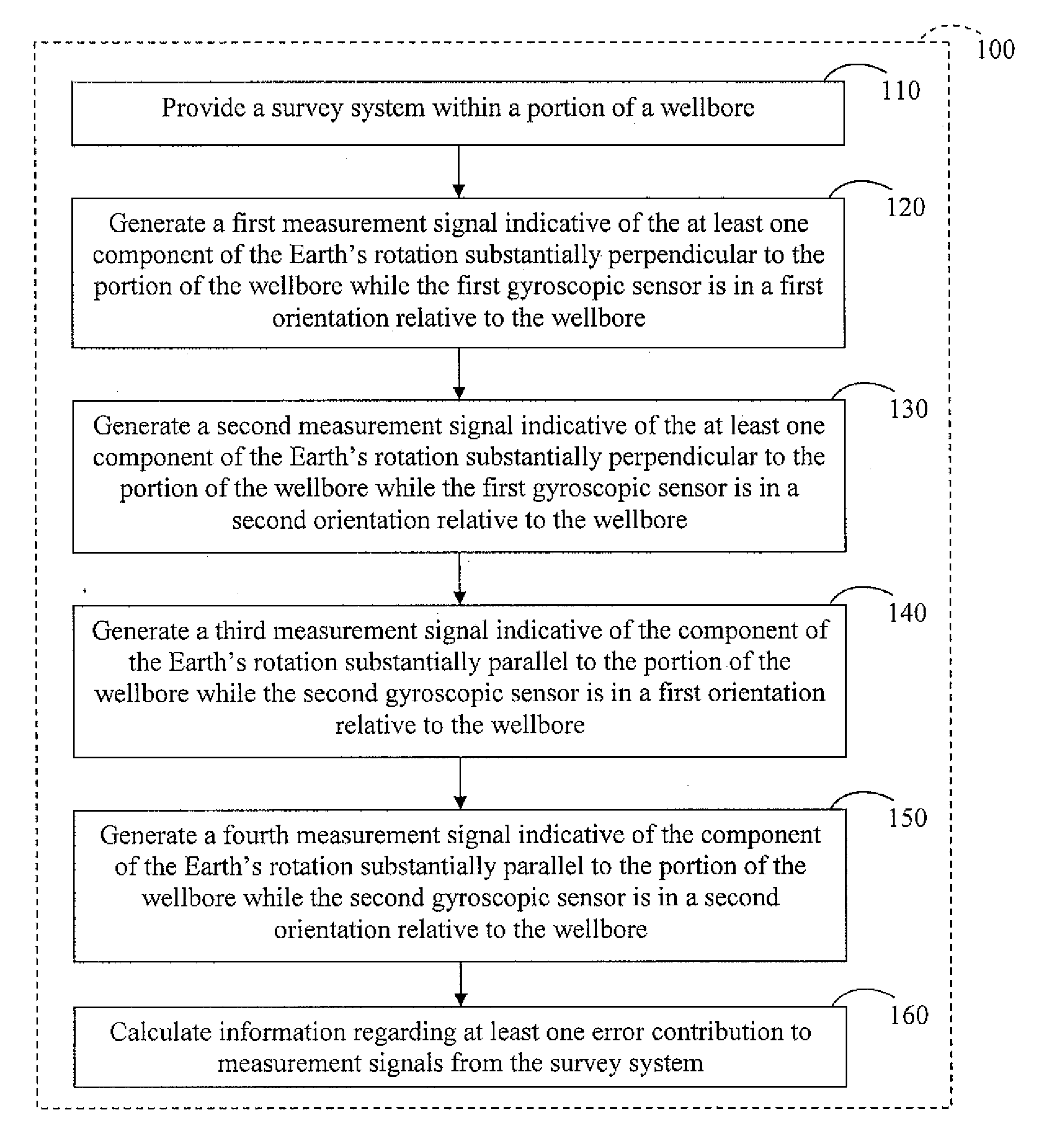
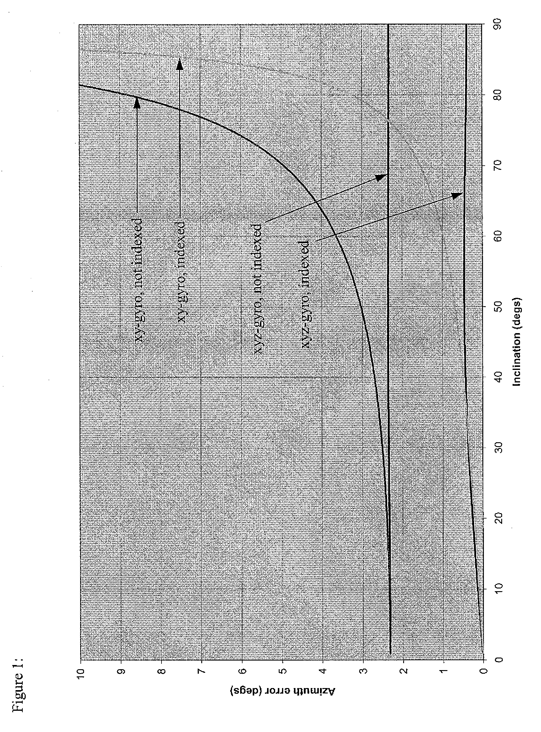
[0022]There is an increasing demand for high accuracy surveys of highly deviated and extended reach wellbores. For example, modern survey systems may operate at any attitude, e.g., at 90 degrees inclination and beyond in horizontal extended reach wells, and high accuracy surveys in such wellbores are desirable.

[0023]While the two-axis strapdown system outlined above provides accurate estimates of wellbore azimuth in a near vertical well, this accuracy degrades as inclination increases, with the azimuth becoming indeterminate due to a singularity in the calculation at 90 degrees inclination. To overcome this limitation, an additional rotation rate measurement about the along-hole or longitudinal (z) axis of the survey tool can be performed.

[0024]While down-hole gyro survey systems incorporating a strapdown gyro mounted to provide the necessary z-axis measurement already exist, there is a need for a sensor configuration that will allow the sensor system to establish the direction of t...


PUM


Abstract

A method reduces error contributions to gyroscopic measurements from a wellbore survey system having two gyroscopic sensors adapted to generate signals indicative of at least one component of the Earth's rotation substantially perpendicular to the wellbore and indicative of a component of the Earth's rotation substantially parallel to the wellbore. The method includes generating a first signal indicative of the at least one substantially perpendicular component while the first sensor is in a first orientation; generating a second signal indicative of the at least one substantially perpendicular component while the first sensor is in a second orientation; generating a third signal indicative of the substantially parallel component while the second sensor is in a first orientation; and generating a fourth signal indicative of the substantially parallel component while the second sensor is in a second orientation. The method further includes calculating information regarding at least one of a mass unbalance offset error and a quadrature bias error using the first, second, third, and fourth signals.

Description

BACKGROUND OF THE INVENTION[0001]1. Field of the Invention[0002]The present application relates generally to systems and method for reducing error contributions to gyroscopic measurements from a wellbore survey system and / or determining the position or orientation of the survey system relative to the Earth.[0003]2. Description of the Related Art[0004]Many wellbore gyroscopic survey systems that are currently in service are based on angular rate measurements taken about two axes only, denoted the x and y axes, that are both substantially perpendicular to the direction along the wellbore (referred to as the “along-hole axis”) and substantially perpendicular to each other. In stationary gyroscopic survey systems, these measurements are used to determine the direction of the survey tool in the wellbore with respect to true north, the tool azimuth angle, using measurements of the horizontal components of Earth's rotation sensed about a measurement axis of the survey tool in a process kno...

Claims


Application Information

Patent Timeline
Patent Type & Authority Applications(United States)
IPC IPC(8): E21B47/00G01C19/00
CPCE21B47/022
Inventor EKSETH, ROGERWESTON, JOHN LIONELUTTECHT, GARY WILLIAM
Owner GYRODATA
Why Eureka
Try Eureka