Pull-based state dissemination between managed forwarding elements
What is AI technical title?
AI technical title is built by Patsnap AI team. It summarizes the technical point description of the patent document.
a forwarding element and state-based technology, applied in the field of pull-based state-based dissemination, can solve the problems of increasing processing difficulty, l2 domains cannot scale to large sizes, and at least one of the others are hampering, so as to avoid the overhead of publishing and overhead cost
Active Publication Date: 2013-08-15
NICIRA
View PDF1 Cites 72 Cited by
Summary
Abstract
Description
Claims
Application Information
AI Technical Summary
This helps you quickly interpret patents by identifying the three key elements:
Problems solved by technology
Method used
Benefits of technology
Benefits of technology
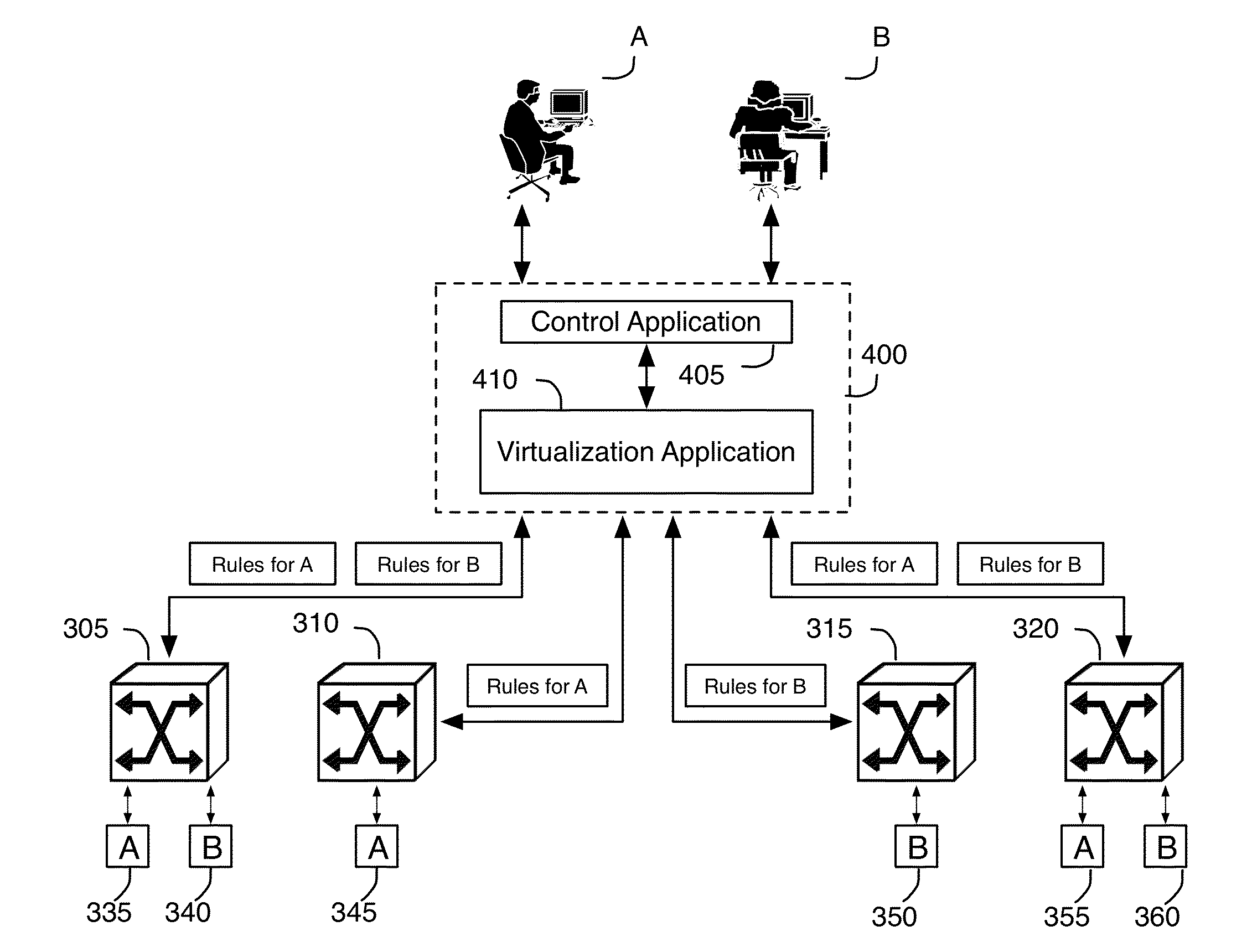
[0013]In some embodiments, each managed switching elements reports its VIFs to the physical controller responsible for the switch. The physical controller then publishes this information to all of the logical controllers. As such, the information flow from the switching elements to the logical controllers is done in a hierarchical manner, but one that is upside down compared to the hierarchy used for computing the flow entries. Because this information may potentially reach more and more controllers as it traverses up the hierarchy, the information should be limited in volume and not overly dynamic. This allows the publication of the information to avoid becoming a scalability bottleneck for the system, while enabling the information to be obtained by the upper layers of the hierarchy as soon as (or very shortly after) the information is generated at the switching elements.
[0015]Instead of requiring all the information needed by the controllers to be published proactively, the network control system of some embodiments has the controllers “pull’ the information from the lower layers as needed. For certain types of information, it may be difficult to determine in advance whether the information is needed by any of the controllers and, if it is needed, which of the controllers needs the information. For this sort of information, the controllers of some embodiments “pull” the information instead of passively receiving information automatically published by the lower layers. This enables the network control system in such embodiments to avoid the overhead of publishing all the information even when the information is not needed. The overhead cost is paid only when the information is actually needed, when the controllers pull the information.
Problems solved by technology
This process is of increased difficulty where the network switching elements are shared across multiple users.
Many approaches taken to address one of these goals results in hampering at least one of the others.
For instance, one can easily provide network mobility for virtual machines within an L2 domain, but L2 domains cannot scale to large sizes.
Furthermore, retaining user isolation greatly complicates mobility.
Method used
Image
Click on the blue label to locate the original text in one second.
Reading with bidirectional positioning of images and text.
Examples
example use cases
[0692]H. Example Use Cases
[0693]1. API
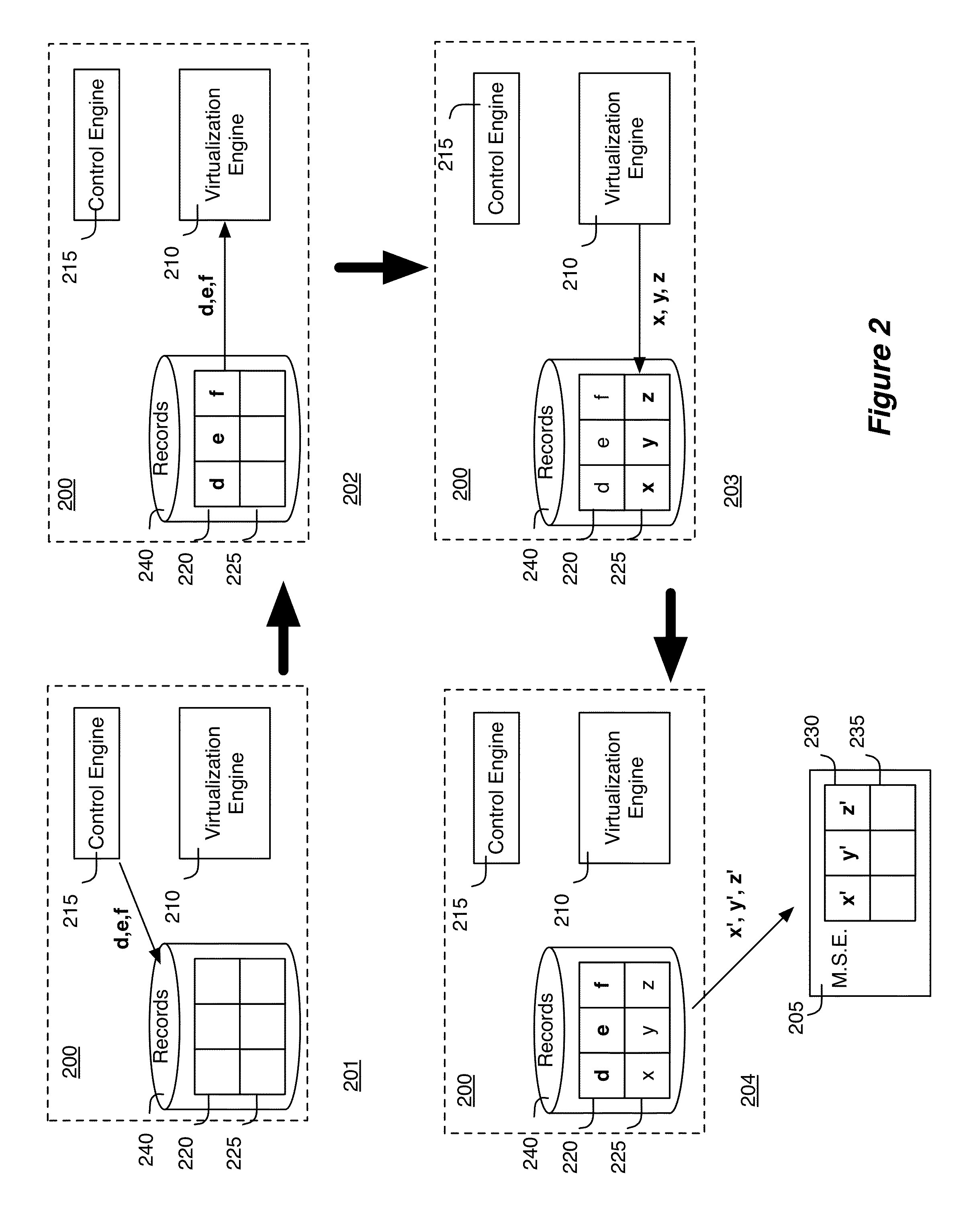
[0694]As mentioned above, the inputs defining LDP sets in the form of API calls are sent to an input translation controller supporting the API. The network control system of some embodiments renders the API updates atomic. That is, a configuration change migrates the system from the old state to the new state in atomic manner. Specifically, after receiving an API call, the API receiving code in the system updates the state for an nLog engine and after feeding all the updates in, the API receiving code in the system waits for a fixedpoint (to let the computation converge) and signals the transaction to be ended by committing the changes for the nLog. After this, the forwarding state updates will be sent downwards to the controllers below in the cluster hierarchy, or towards the switching elements—all in a single transactional update. The update will be applied in a transactional manner by the receiving element.
[0695]In some embodiments, the API u...
PUM
Abstract
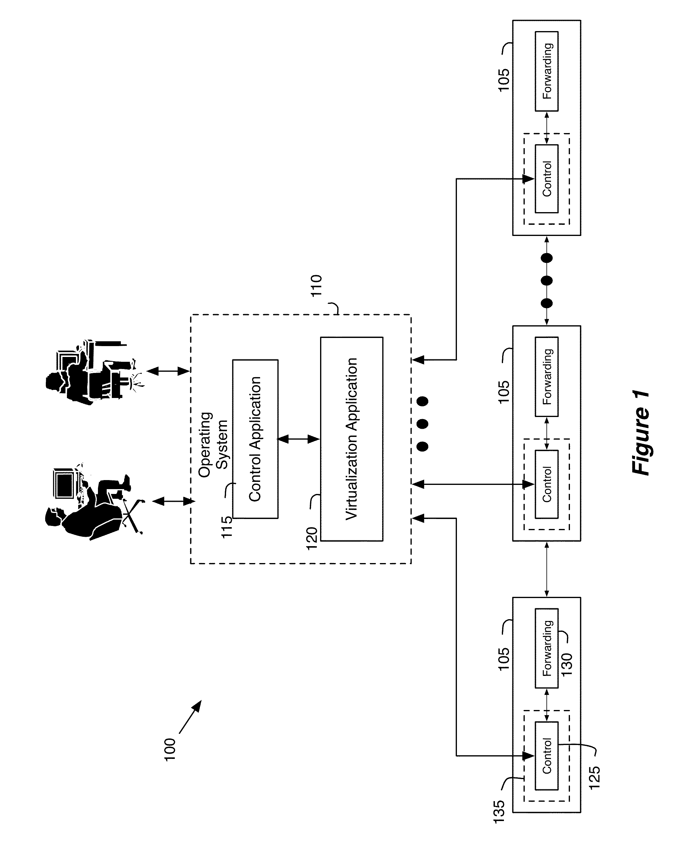
For a controller that manages managed forwarding elements that forward data in a network, a method for configuring the managed forwarding elements is described. The method computes forwarding state and pushes the computed forwarding state to the managed switching elements. The forwarding state defines forwarding behaviors of the managed switching elements. The method configures the managed switching elements to exchange forwarding state with each other. The method configures the managed switching elements by configuring a first managed forwarding element to send a forwarding state information request to a second managed forwarding element and by configuring the second managed forwarding element to (1) respond to the forwarding state information request by looking up a forwarding state information repository and (2) update the forwarding state information repository with forwarding states information received from a third managed forwarding element.
Description
CLAIM OF BENEFIT TO PRIOR APPLICATIONS[0001]This application is a continuation application of U.S. patent application Ser. No. 13 / 589,077, filed on Aug. 17, 2012. U.S. patent application Ser. No. 13 / 589,077 claims the benefit of U.S. Provisional Application 61 / 551,425, filed Oct. 25, 2011; U.S. Provisional Application 61 / 551,427, filed Oct. 25, 2011; U.S. Provisional Application 61 / 577,085, filed Dec. 18, 2011; U.S. Provisional Application 61 / 595,027, filed Feb. 4, 2012; U.S. Provisional Application 61 / 599,941, filed Feb. 17, 2012; U.S. Provisional Application 61 / 610,135, filed Mar. 13, 2012; U.S. Provisional Application 61 / 635,056, filed Apr. 18, 2012; U.S. Provisional Application 61 / 635,226, filed Apr. 18, 2012; and U.S. Provisional Application 61 / 647,516, filed May 16, 2012. This application claims the benefit of U.S. Provisional Application 61 / 595,027, filed Feb. 4, 2012; U.S. Provisional Application 61 / 599,941, filed Feb. 17, 2012; U.S. Provisional Application 61 / 610,135, filed...
Claims
Application Information
Patent Timeline
Application Date:The date an application was filed.
Publication Date:The date a patent or application was officially published.
First Publication Date:The earliest publication date of a patent with the same application number.
Issue Date:Publication date of the patent grant document.
PCT Entry Date:The Entry date of PCT National Phase.
Estimated Expiry Date:The statutory expiry date of a patent right according to the Patent Law, and it is the longest term of protection that the patent right can achieve without the termination of the patent right due to other reasons(Term extension factor has been taken into account ).
Invalid Date:Actual expiry date is based on effective date or publication date of legal transaction data of invalid patent.
Patent Type & AuthorityApplications(United States)

