Compound Action Snips

Active Publication Date: 2013-09-12
ALLPROFESSIONAL MFG
View PDF4 Cites 8 Cited by
  • Summary
  • Abstract
  • Description
  • Claims
  • Application Information

AI Technical Summary

Problems solved by technology

However, the second fastener exposed out of the external surface of the handle results in u

Method used


Image

  • Compound Action Snips
  • Compound Action Snips
  • Compound Action Snips

Examples


Embodiment Construction

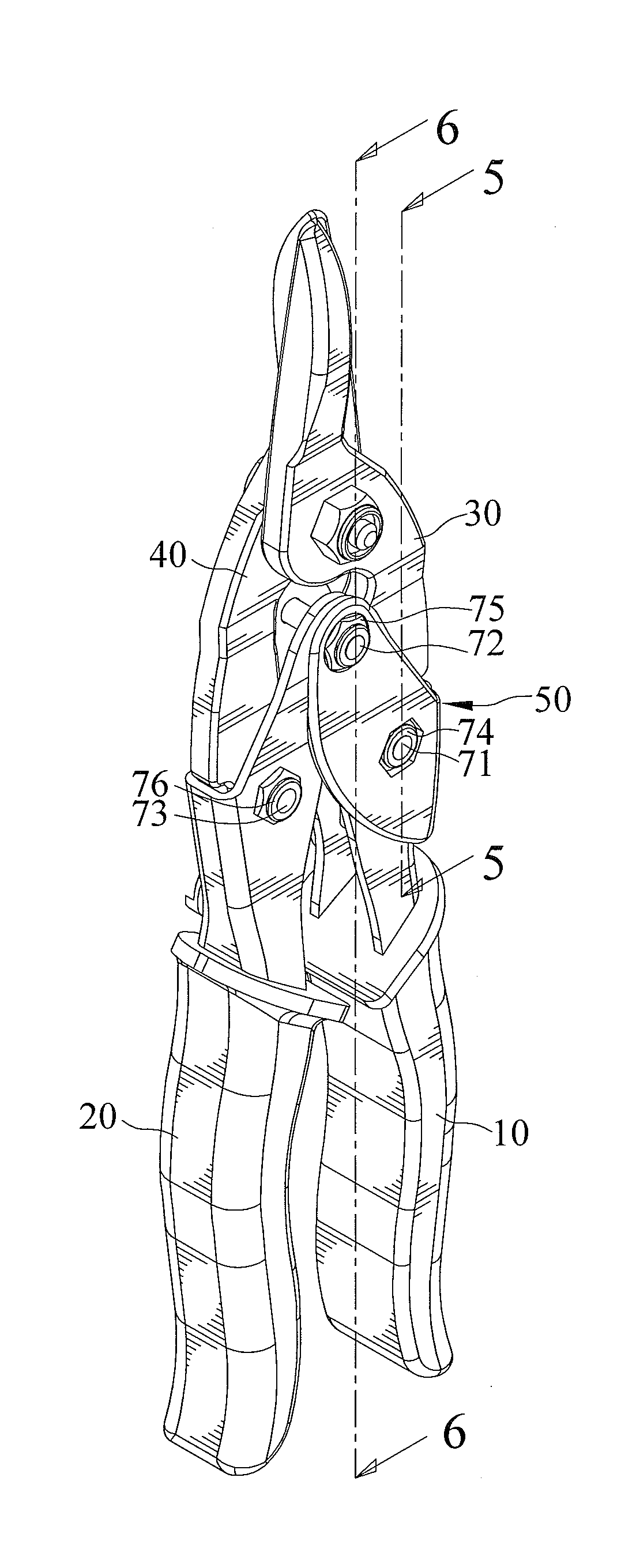
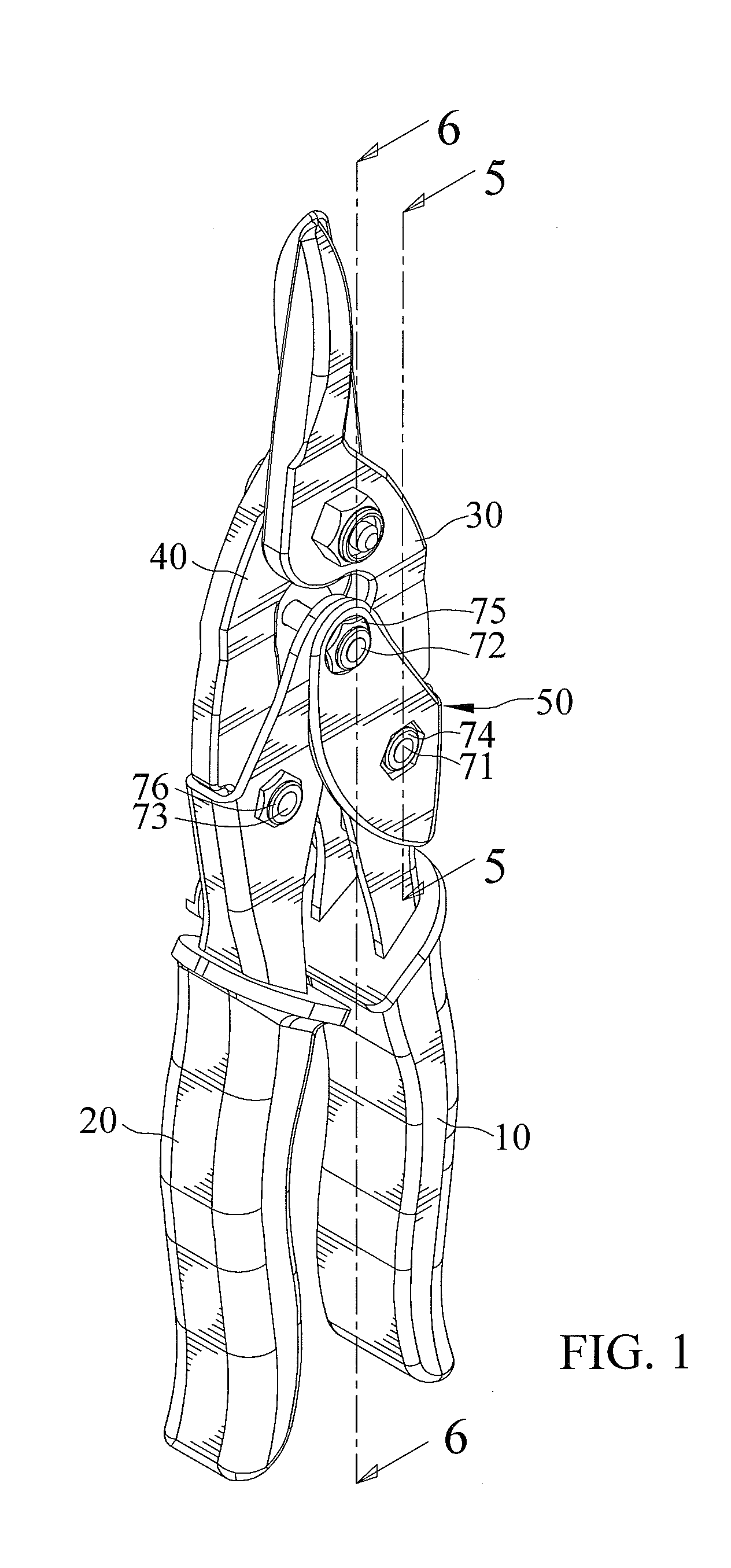
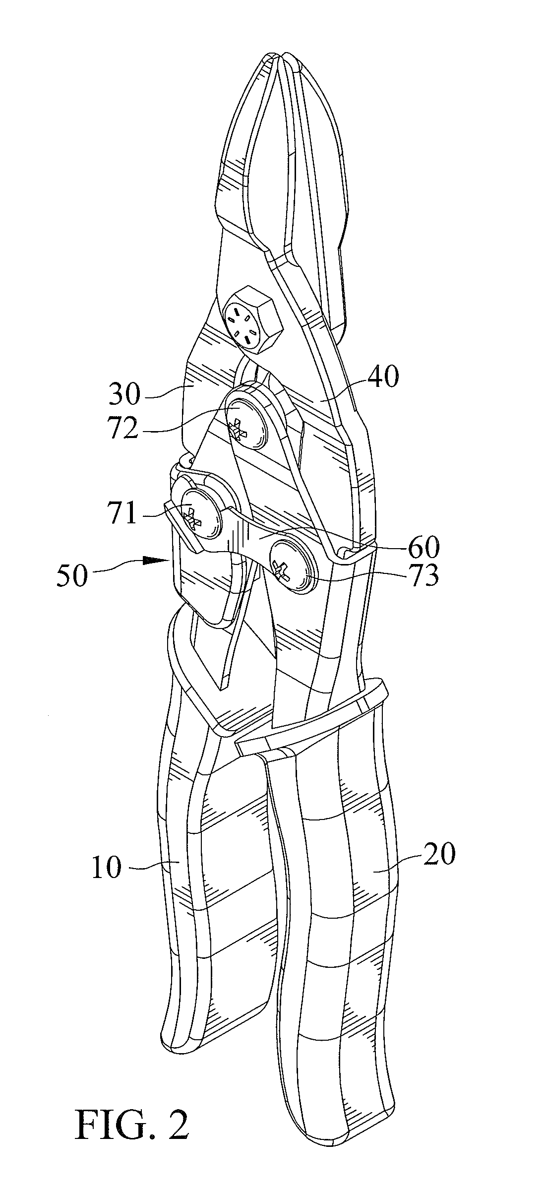
[0032]Referring to FIGS. 1 through 6, a compound action snips according to the first embodiment of the present invention generally includes first and second handles 10 and 20, first and second blades 30 and 40, and a nameplate 50 therein. The first and second handles 10 and 20 are mutually pivotally connected at a second fastener 72 fastened with a second fixing element 75. The first and second blades 30 and 40 are respectively mounted to the first and second handles 10 and 20 by first and third fasteners 71 and 73 respectively fastened with first and third fixing elements 74 and 76, wherein the first, second, and third fasteners 71, 72, and 73 may comprise bolts, as shown in the figures, or any suitable fasteners, and the first, second, and third fixing elements 74, 75, and 76 may comprise nuts.

[0033]The first handle 10 includes first distal and first proximal ends 11 and 12 disposed opposite to each other therein. The first distal end 11 provides a user to grip thereon. The first ...


PUM


Abstract

A compound action snips includes first and second handles pivotally connected to each other, and first and second blades. The first handle includes first and second walls arranged opposite to each other. The second wall includes a recess. The first blade is mounted to the first handle. The second blade is mounted to the second handle. A fastener inserts into the first wall, the first blade, and the second wall. A fixing element is received into the recess and threaded onto the fastener, so that a top surface defined on the fixing element is not exposed out of the second wall of the first handle.

Description

[0001]The present application is a continuation-in-part application of U.S. patent application Ser. No. 13 / 413,708, now abandoned, filed on Mar. 7, 2012, of which the entire disclosure is incorporated herein.BACKGROUND OF THE INVENTION[0002]1. Field of the Invention[0003]The present invention relates to a compound action snips, and more particularly, to a compound action snips which is able to cut an object without being interfered with the object.[0004]2. Description of the Related Art[0005]U.S. Pat. No. 6,189,219 shows a compound action snips includes a pair of handles mutually connected at a second fastener and a pair of cutting blades connected to the handles. The blades each having a proximal end attached to a distal portion of one of the handles, and the blades are mutually connected at a blade pivot, so that converging movement of the handles causes converging movement of the blades. However, the second fastener exposed out of the external surface of the handle results in und...

Claims


Application Information

Patent Timeline
IPC IPC(8): B26B13/28
CPCB26B13/26
Inventor HUANG, HSIN-TE
Owner ALLPROFESSIONAL MFG
Why Eureka
Try Eureka