Method for preparing metal enclosure of seamless USB connector

A metal shell and connector technology, applied in the field of metal shell preparation, can solve problems such as affecting the appearance and quality of metal shells, reducing product market competitiveness, and complicated drawing mold operations, achieving seamless appearance and improving market performance. Competitiveness and sales, the effect of improving aesthetics and quality

Active Publication Date: 2017-01-11
JIANGSU JUJIE ELECTROMECHANICAL CO LTD
View PDF6 Cites 1 Cited by
  • Summary
  • Abstract
  • Description
  • Claims
  • Application Information

AI Technical Summary

Problems solved by technology

When punching, the punch presses the material in the product area on the belt through the upper and lower pressing dies, and then directly flushes away the material in the waste area connected to the material in the product area through the punching knife, which is simple and fast. When the punching knife is shearing, the material in the product area will be pulled under force, so the side corners of the material in the product area (i.e. the corners of the butt end face 33 of the shell) will form an R angle (such as figure 2 As shown), this will result in a collapsed gap 36 left after the butt joint of the two shells is completed, which affects the appearance and quality of the metal shell, and for the manufacturer, this will reduce the market competitiveness of the product , affecting its sales, which is unacceptable for users who pursue perfection
[0004] In order to solve the above problems, some existing manufacturers have thought of manufacturing the dovetail and dovetail grooves of the butt end faces of the shells through stretching dies to reduce the gaps in the butt joints. However, the operation of the stretching dies is more complicated, and the more important point is that it greatly increases the manufacturing cost

Method used


Image

  • Method for preparing metal enclosure of seamless USB connector
  • Method for preparing metal enclosure of seamless USB connector
  • Method for preparing metal enclosure of seamless USB connector

Examples


Embodiment Construction

[0033] In order to make the purpose, technical solutions and advantages of the embodiments of the present invention clearer, the technical solutions in the embodiments of the present invention will be clearly and completely described below in conjunction with the drawings in the embodiments of the present invention. Obviously, the described embodiments It is a part of embodiments of the present invention, but not all embodiments. Based on the embodiments of the present invention, all other embodiments obtained by persons of ordinary skill in the art without creative efforts fall within the protection scope of the present invention.

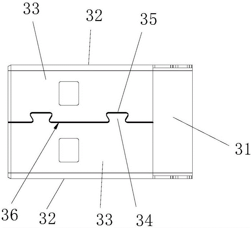
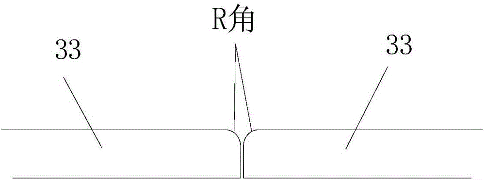
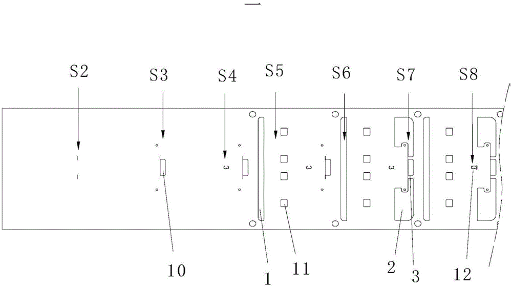
[0034] An embodiment of the present invention provides a method for manufacturing a metal shell of a seamless USB connector, which will be described in detail below with reference to the accompanying drawings. image 3 , Figure 4 with Figure 5 is a schematic diagram of the strip corresponding to the method of the present invention, please refe...


PUM


Abstract

The invention discloses a preparing method for a metal shell of a seamless USB connector, comprising processing a separation hole of the shell front end of a material belt, a vice punching hole,a punching forked tail part, a forked tail slot as well as bending formation treatment and riveting treatment, wherein in the steps of punching forked tail part and forked tail slot, the upper and lower faces of materials in snip die pressing garbage area are fixed by the upper pressing die and lower die of punching tearing equipment, and then the materials in the product area are cut by an upper die punching cutter, so that the corners at the two sides of the area are right angle after the materials in the product area are separated from the product in garbage area; when the direct angle joint surfaces with right angle are in joint connection, the collapse is not allowed, the gap of the joint part of the metal shell is effectively reduced, seamless appearance effect is realized; the appearance and quality of the metal shell are improved, and the market competition and sales of the connector product are improved. In addition, the preparing method in the invention has simple process, convenient operation and low manufacturing cost.

Description

technical field [0001] The invention relates to the technical field of USB connectors, in particular to a method for preparing a metal shell of a seamless USB connector. Background technique [0002] Existing USB connectors generally consist of a metal shell and a rubber core body with a terminal set. Among them, such as figure 1 As shown, the metal shell of the USB connector is generally in the shape of a hollow rectangle, with a shell bottom 31, two shell sides 32, a shell butt end 33 with a dovetail 34 and another shell butt end 33 with a dovetail 35 , during molding, the dovetail portion 34 and the dovetail groove 35 of the abutting end surface 33 of the housing are butted with each other. [0003] In the traditional manufacturing process of the metal shell of the USB connector, people usually use a punch to form the dovetail portion and the dovetail groove on the butt end surface of the shell. When punching, the punch presses the material in the product area on the b...

Claims


Application Information

Patent Timeline
Patent Type & Authority Applications(China)
IPC IPC(8): H01R43/18
CPCH01R43/18
Inventor 李良浩
Owner JIANGSU JUJIE ELECTROMECHANICAL CO LTD
Why Eureka
Try Eureka