
Exhaust post-treatment device and method for a vehicle, with a reductant vaporising surface being warmed by a peltier element
a technology of exhaust post-treatment and reductant, which is applied in the direction of exhaust treatment electric control, machines/engines, mechanical apparatus, etc., to achieve the effects of reducing nitrogen oxides, high efficiency, and robust configuration
- Summary
- Abstract
- Description
- Claims
- Application Information
AI Technical Summary
Benefits of technology
Problems solved by technology
Method used
Image

Examples
first embodiment
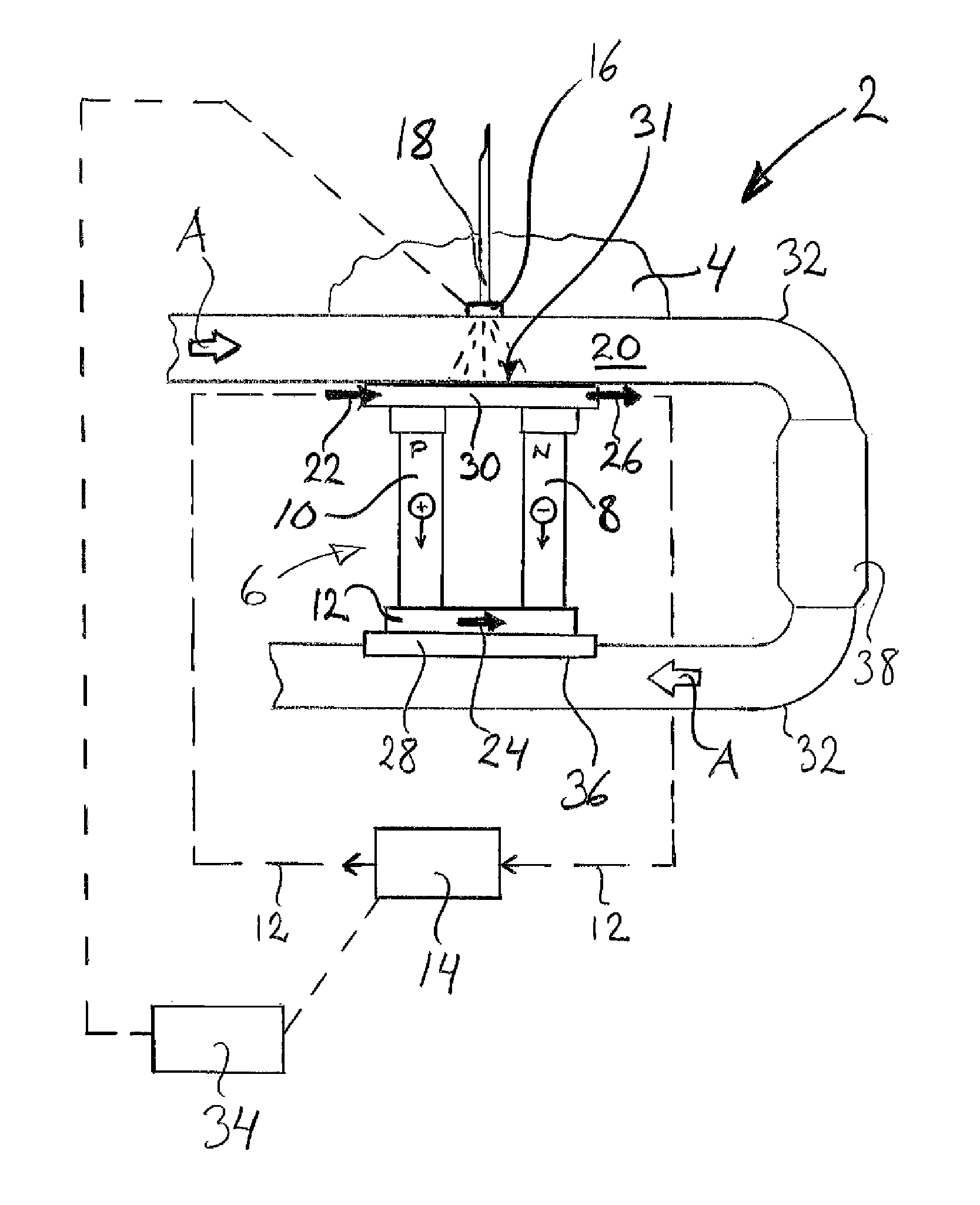
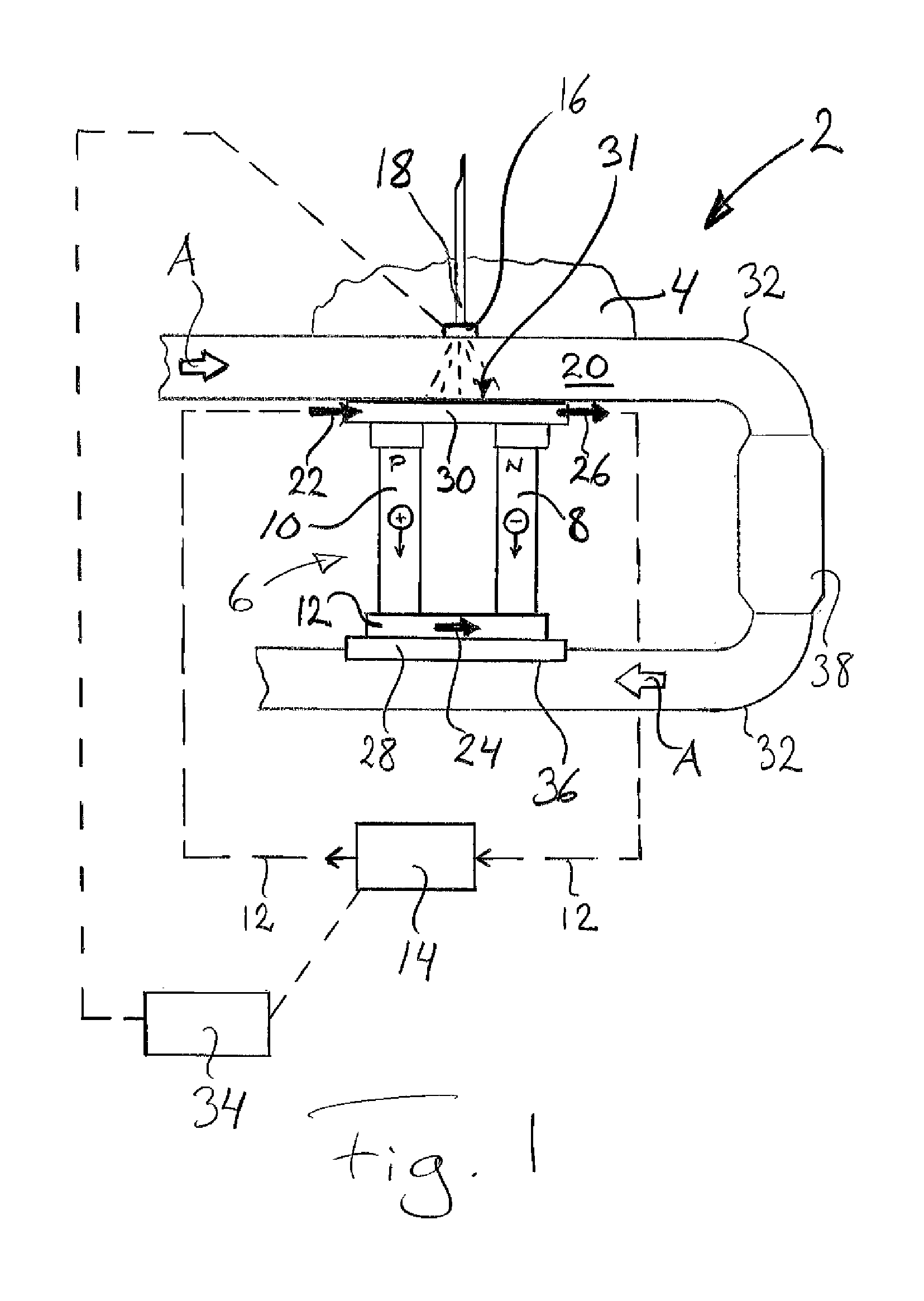
[0022]FIG. 1 depicts schematically an exhaust post-treatment device 2 for a vehicle 4 according to the invention, which device 2 comprises a Peltier element 6 also called a thermoelectric cooling element. The Peltier element 6 itself comprises at least one “thermocouple” composed of two electrodes 8, 10 made of different semiconductive metals such that every second electrode 8 is of N type and the alternate electrodes 10 are of P type, which electrodes 8, 10 are arranged to extend from one side 28 of the Peltier element 6 to the other side 30 of the Peltier element 6 and are connected in series via conductors 12, preferably made of copper, to a direct-current source 14, such that closing the electric circuit causes electrons in the N type electrode to move in an opposite direction to the current, and holes in the P type electrode to move in the direction of the current, as illustrated in the diagram, both of them diverting heat from one side 28 of the Peltier element 6 to the other ...
second embodiment
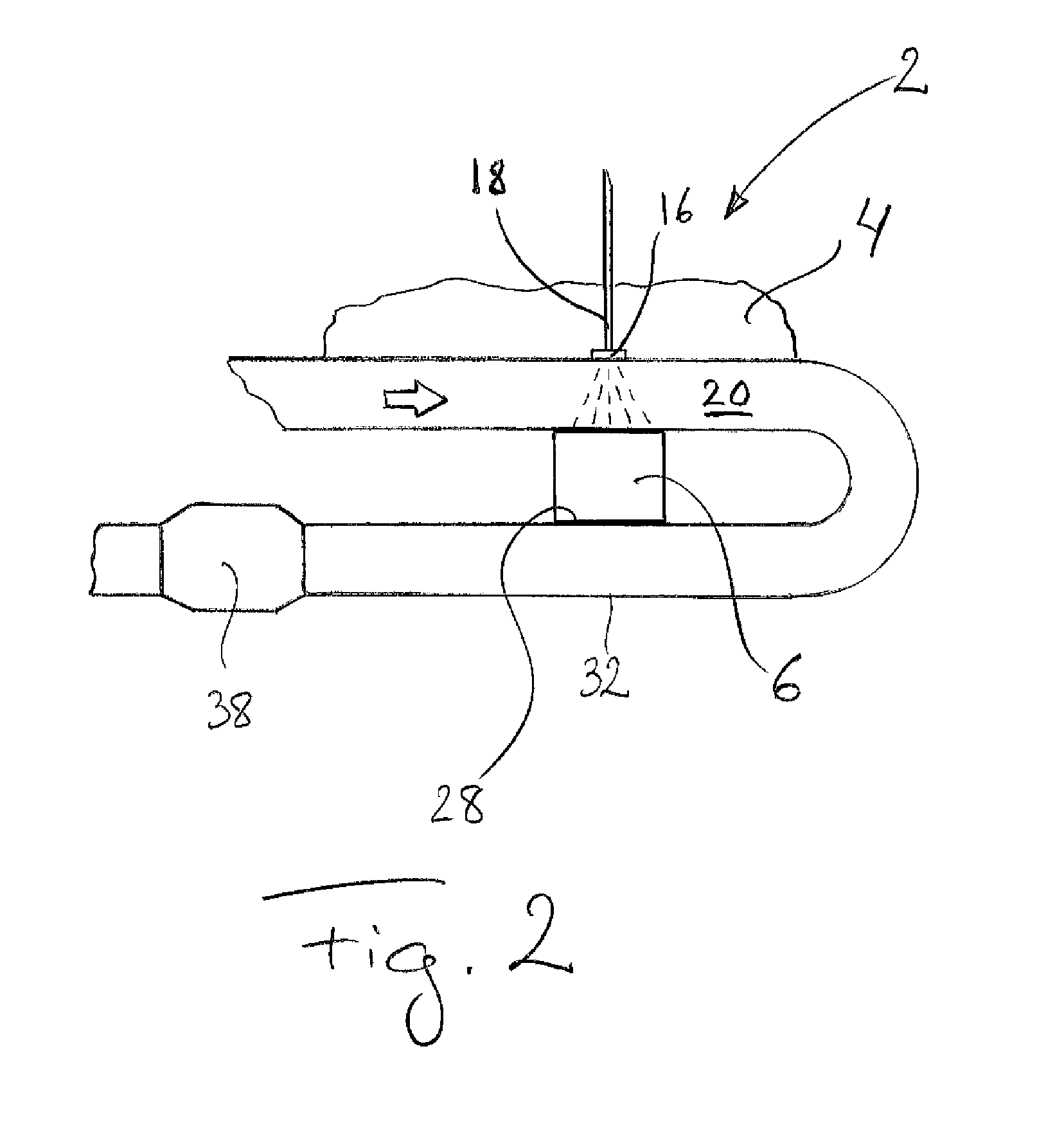
[0041]FIG. 2 depicts schematically an exhaust post-treatment device 2 for a vehicle 4 according to the invention, which device 2 comprises a Peltier element 6. The device 2 comprises also a supply device 16 for supply to the exhaust gases 20 of liquid reducing agent 18 intended for reduction of nitrogen oxides present in them.
[0042]The embodiment depicted in FIG. 2 differs from that described with reference to FIG. 1 in that in this case the heat absorption side 28 of the Peltier element 6 is adjacent to the outside of an exhaust pipe 32, and that a possible catalyst 38 is provided downstream of the heat absorption side 28 of the Peltier element 6. The catalyst 38 may however also be situated upstream of the heat absorption side 28 of the Peltier element 6, as in FIG. 1, or alternatively the exhaust post-treatment device may be used with no catalyst. In other respects, the description with respect to FIG. 1 applies also, e.g. as regards a possible control unit, in FIG. 2.
third embodiment
[0043]FIG. 3 depicts schematically an exhaust post-treatment device 2 for a vehicle 4 according to the invention, which device 2 comprises a Peltier element 6. The device 2 likewise comprises a supply device 16 for supply to the exhaust gases 20 of liquid reducing agent 18 intended for reduction of nitrogen oxides present in them.
[0044]The embodiment depicted in FIG. 3 differs from that described with respect to FIG. 1 in that in this case the heat absorption side 28 of the Peltier element 6 is upstream of the supply device 16 for supply of liquid reducing agent 18 to the exhaust gases 20. In other respects, the description with respect to FIG. 1 applies also, e.g. as regards a possible control unit, to the embodiment depicted in FIG. 2 but any catalyst 38 has to be situated downstream of the supply device 16 for supply of liquid reducing agent 18 to the exhaust gases 20.
PUM
 Abstract
Description
Claims
Application Information