High-voltage power switch with a switch gap

a high-voltage power switch and switch gap technology, applied in the direction of air-break switch, high-tension/heavy-dress switch, electrical equipment, etc., to achieve the effect of reducing flow resistan

Inactive Publication Date: 2014-03-04
SIEMENS ENERGY GLOBAL GMBH & CO KG
View PDF19 Cites 4 Cited by
  • Summary
  • Abstract
  • Description
  • Claims
  • Application Information

AI Technical Summary

Benefits of technology

[0031]A hollow truncated conical section of the switching gas inlet channel wall may be shaped to correspond to a widening switching gas inlet channel. On the one hand, a reducing flow resistance is made available along the path of the flow inlet channel, in the interior of the switching gas inlet channel. The positioning of the reverse-flow channel allows the flow inlet channel to also be used, at least in places, for emptying the storage volume. This allows direction changing and onward guidance of hot switching gases in an advantageous manner from the flow point of view within a compact storage volume, in a small physical space.
[0032]A further advantageous refinement allows the flow guide device to be kept at a distance from the walls of the storage volume via at least one stud bolt, which produces stressing forces running in the flow direction.

Problems solved by technology

When large amounts of switching gas are created during short time periods, it may, however, be necessary to introduce the large amounts of switching gas into the storage volume as quickly as possible.

Method used


Image

  • High-voltage power switch with a switch gap
  • High-voltage power switch with a switch gap
  • High-voltage power switch with a switch gap

Examples


Embodiment Construction

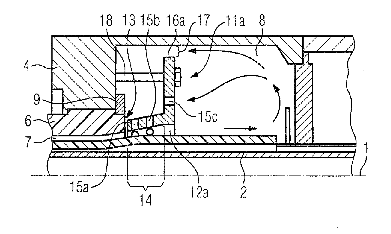
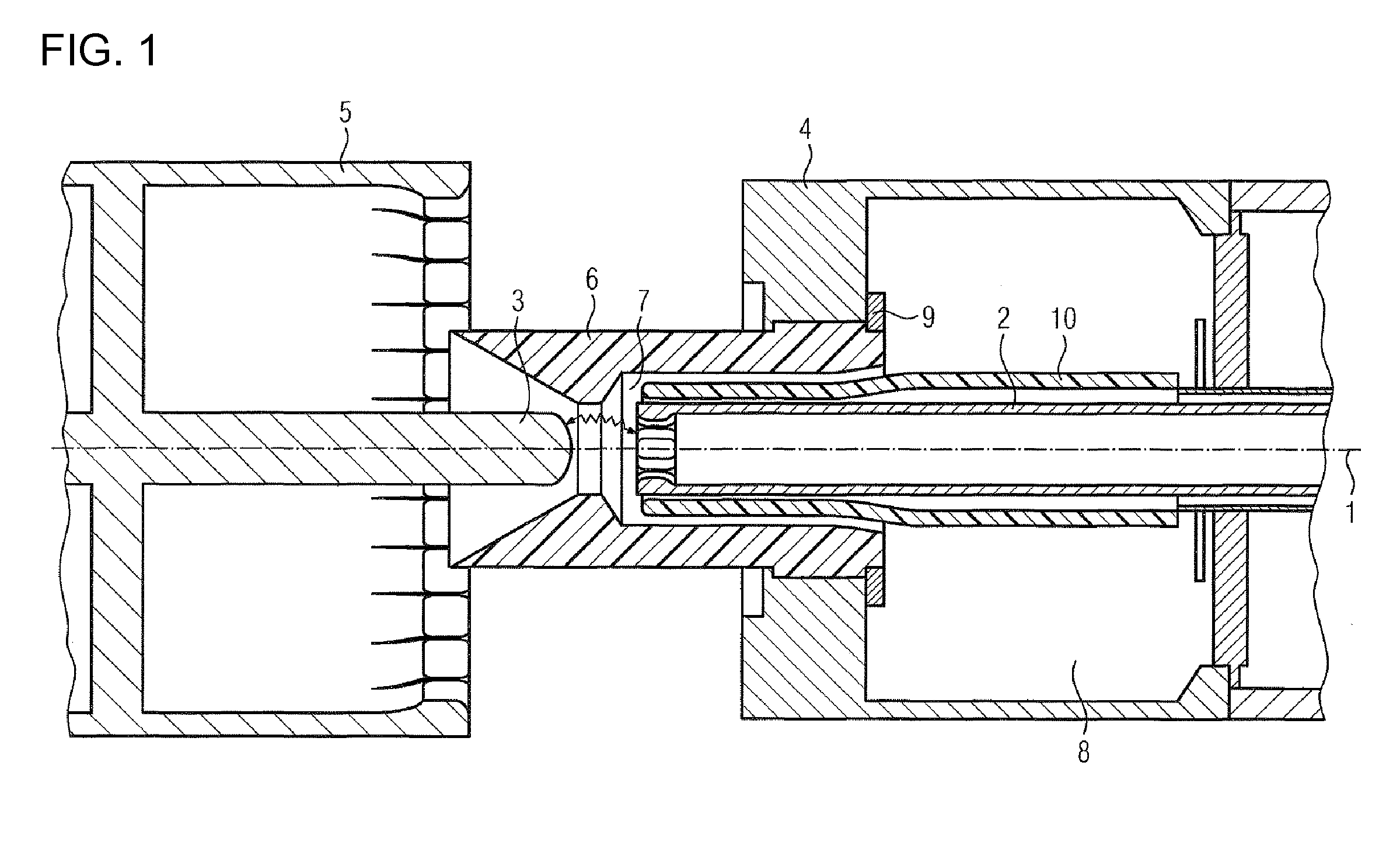
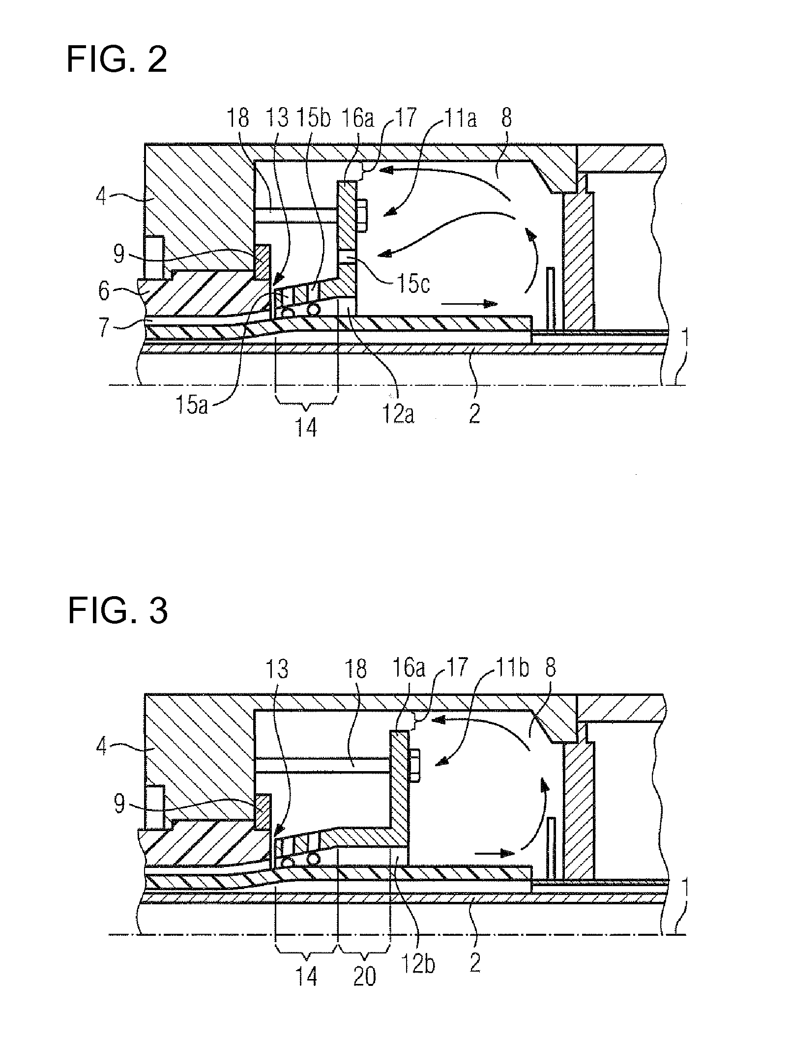
[0039]FIG. 1 shows a section view of a detail of an interrupter unit of a high-voltage circuit breaker. The interrupter unit of the high-voltage circuit breaker is formed substantially coaxially with respect to a longitudinal axis 1. The interrupter unit of the high-voltage circuit breaker has a first arc contact piece 2 and a second arc contact piece 3. The two arc contact pieces 2, 3 are aligned coaxially with respect to the longitudinal axis 1, and are arranged opposite one another. In this case, that end of the first arc contact piece 2 which faces the second arc contact piece 3 is equipped with a contact element which is in the form of a bush and has a plurality of contact fingers. The second arc contact piece 3 is in the form of a bolt, and is designed for insertion into the contact element, which is in the form of a bush, on the first arc contact piece 3.

[0040]A first rated current contact piece 4 is arranged coaxially with respect to the first arc contact piece 2. A second r...


PUM


Abstract

A high-voltage power switch has a switch gap surrounded by a nozzle made of insulating material. The nozzle of insulating material is formed with a switching gas channel. The switching gas channel opens up into a storage volume. A flow steering apparatus is disposed within the storage volume. The flow steering apparatus has a switching gas entrance channel. An annular gap is formed between the wall in which the switching gas channel opens up and a switching gas entrance channel wall that borders the switching gas channel.

Description

BACKGROUND OF THE INVENTIONField of the Invention[0001]The invention relates to a high-voltage circuit breaker having a switching gap which is at least partially surrounded by an insulating material nozzle which has a switching gas channel which opens in a storage volume, and having a flow guide device, which is arranged at least partially within the storage volume.[0002]By way of example, a high-voltage circuit breaker such as this is known from European Patent Application EP 0 783 173 A1, which describes a high-voltage circuit breaker which has a switching gap which is surrounded by an insulating material nozzle. The insulating material nozzle has a switching gas channel which opens in a storage volume. A flow guide device is arranged within the storage volume. The flow guide device has a valve, which opens and closes a recess as required. In this case, the flow guide device is arranged such that temporary storage of switching gas in the storage volume is controlled by the positio...

Claims


Application Information

Patent Timeline
Patent Type & Authority Patents(United States)
IPC IPC(8): H01H33/88
CPCH01H33/88H01H2033/888
Inventor BOSE, SHIBANI
Owner SIEMENS ENERGY GLOBAL GMBH & CO KG
Why Eureka
Try Eureka