Composite structure and methods of assembling same

a technology of composite materials and pultrusion rods, which is applied in the field of composite structures, can solve the problems of reducing the ability of a load force to be transferred, affecting the quality of pultrusion rods, and requiring time-consuming, complex and/or costly maneuvering of pultrusion rods

Active Publication Date: 2013-09-12
THE BOEING CO
View PDF4 Cites 3 Cited by
  • Summary
  • Abstract
  • Description
  • Claims
  • Application Information

AI Technical Summary

Benefits of technology

This patent text describes a composite structure that includes a base member with an inner surface that defines a channel, a support member attached to the outer surface, and a fabric overwrap attached to the support member. The method of assembly involves extruding the base member and then attaching the fabric overwrap to the support member. The technical effect of this invention is a composite structure that provides enhanced strength and durability while also being lightweight and flexible. This makes it ideal for use in various applications such as aircraft fuselages, where weight is a critical factor.

Problems solved by technology

However, such a process may require time-consuming, complex, and / or costly maneuvering of the pultruded rods within and / or through the fibers.
Moreover, in some composite structures, the integration of the pultruded rod, which has a different stiffness than the braided fibers, may result in microcracking between the pultruded rod and the surrounding resin.
Furthermore, depending on the length of the pultruded rods, stress concentrations may occur near the rod such that any cracking and / or debonding may reduce the ability of a load force to be transferred between the rod and the structural component.

Method used


Image

  • Composite structure and methods of assembling same
  • Composite structure and methods of assembling same
  • Composite structure and methods of assembling same

Examples


Embodiment Construction

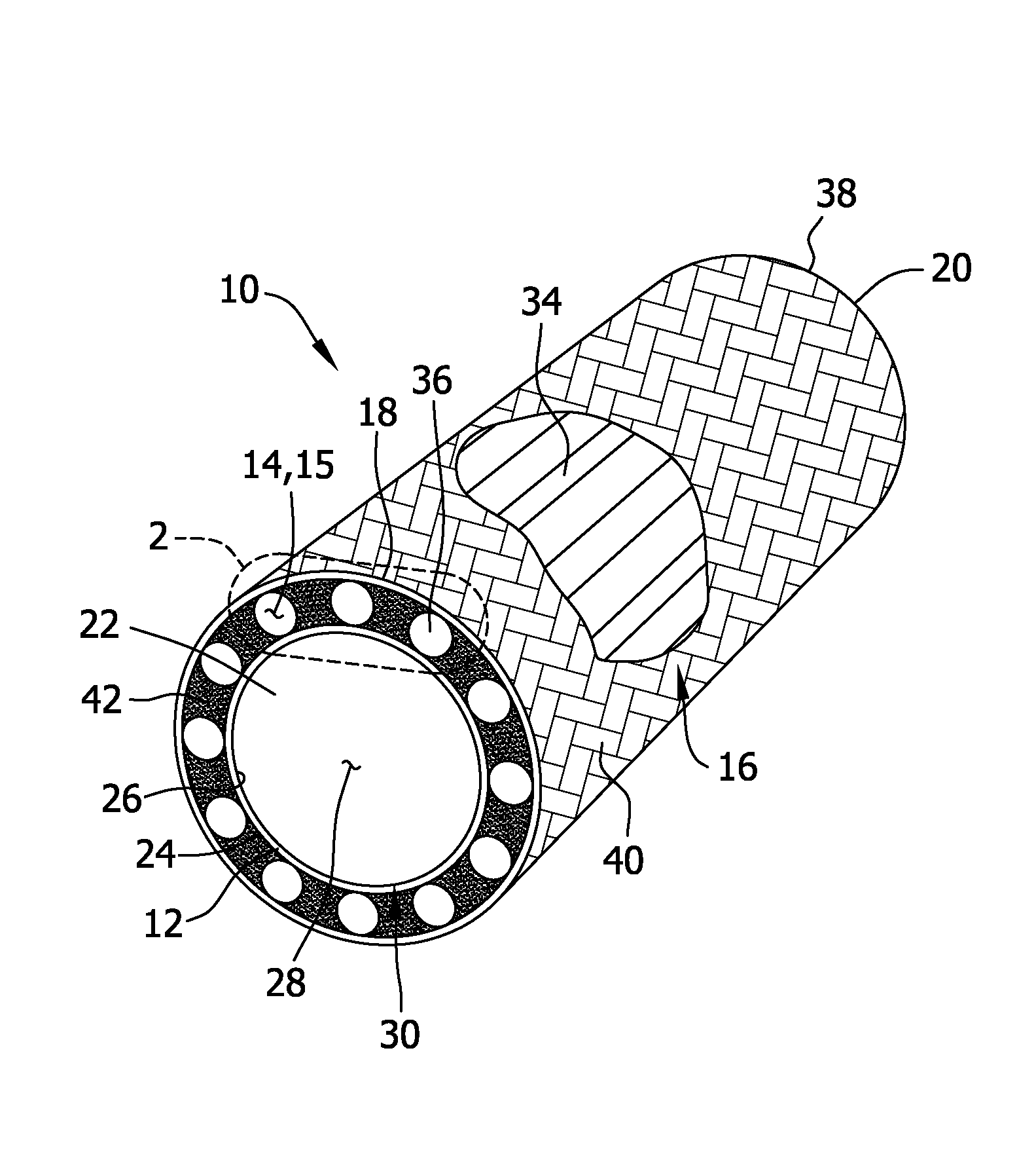
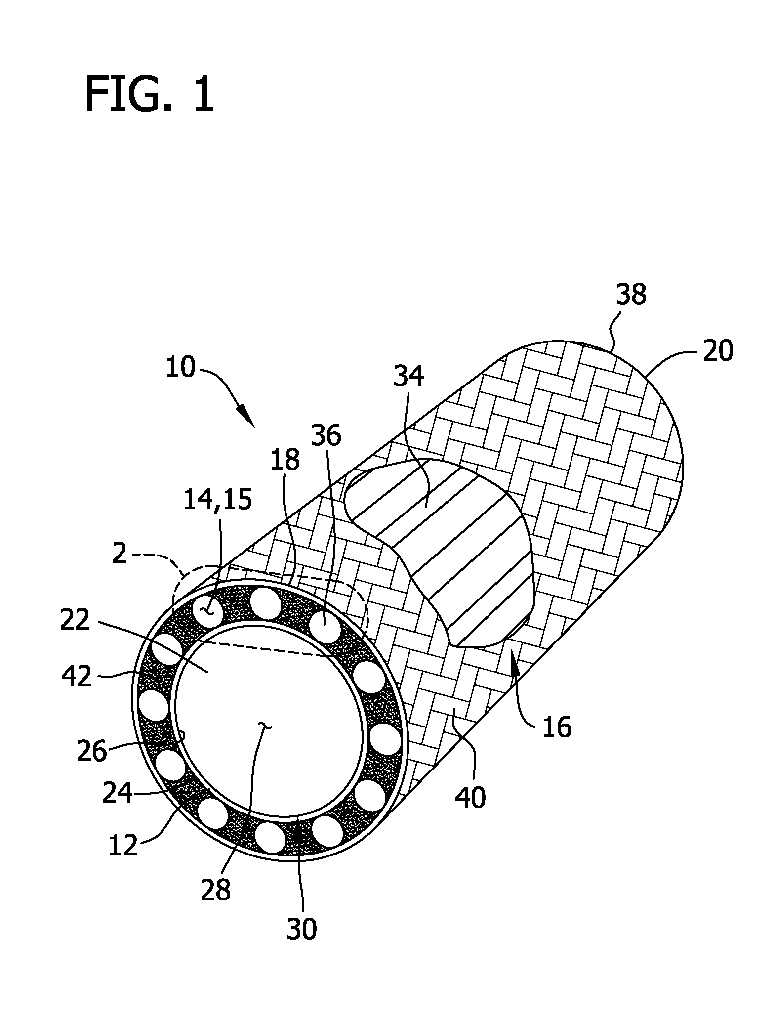
[0017]The embodiments described herein relate to a resilient composite structure and methods of assembling the composite structure. Generally, the embodiments described herein relate to a self-supporting, lightweight support section for use in liquid molding that may be utilized with a plurality of materials to provide a composite structure having a predetermined stiffness and weight. Moreover, the composite structure may be utilized in a variety of environments such as, but not limited to, military, industrial and consumer environments. In one embodiment, the composite structure described herein is utilized with an aircraft fuselage. It should be understood that the description and figures that utilize fuselages are exemplary only.

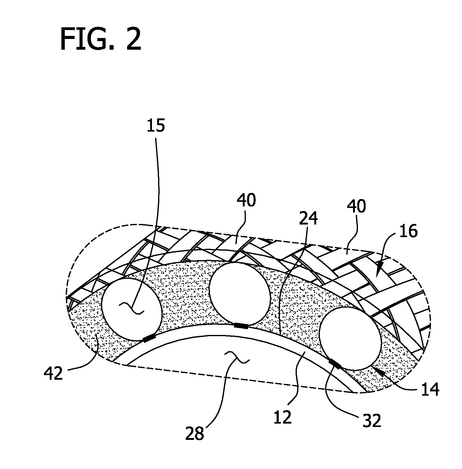
[0018]FIG. 1 illustrates a cross-sectional view of an exemplary composite structure 10. FIG. 2 illustrates a partial cut-away view of composite structure 10. Composite structure 10 facilitates providing structural support to structural components (not sho...


PUM

PropertyMeasurementUnit
Electrical conductivityaaaaaaaaaa
Structureaaaaaaaaaa
Shapeaaaaaaaaaa

Abstract

A composite structure and method of assembling a composite structure is provided. The composite structure includes a base member having an outer surface and an inner surface. The inner surface defines a channel therethrough. The composite structure further includes a support member coupled to the outer surface. A fabric overwrap is coupled to the support member.

Description

BACKGROUND OF THE INVENTION[0001]The present disclosure relates generally to a composite structure and, more specifically, to composite structures utilized to support structural components, and methods of assembling the same.[0002]Composite materials, consisting of fibers and resin, are used to produce a wide range of useful structural components. Such composite structures have advantages over structures fabricated from other materials such as, but not limited to, strength-to-weight ratios approaching those of structural alloys. Several processes for forming composite structures are common Some of these known processes may require the formation of a “layup” or preform of fibrous material, which generally takes the contours of the finished structural components. This layup or preform may be formed of a fabric of structural fibers or of individual fibers themselves, and may be “laid up” against a mandrel, either manually or by a mechanized apparatus. In one such fabrication method, th...

Claims


Application Information

Patent Timeline
IPC IPC(8): B32B1/08B29C63/06
CPCB29C70/542Y10T428/13B29C70/68
Inventor TSOTSIS, THOMAS KARL
Owner THE BOEING CO
Why Eureka
Try Eureka