Low Power, Multi-Chip Diversity Architecture
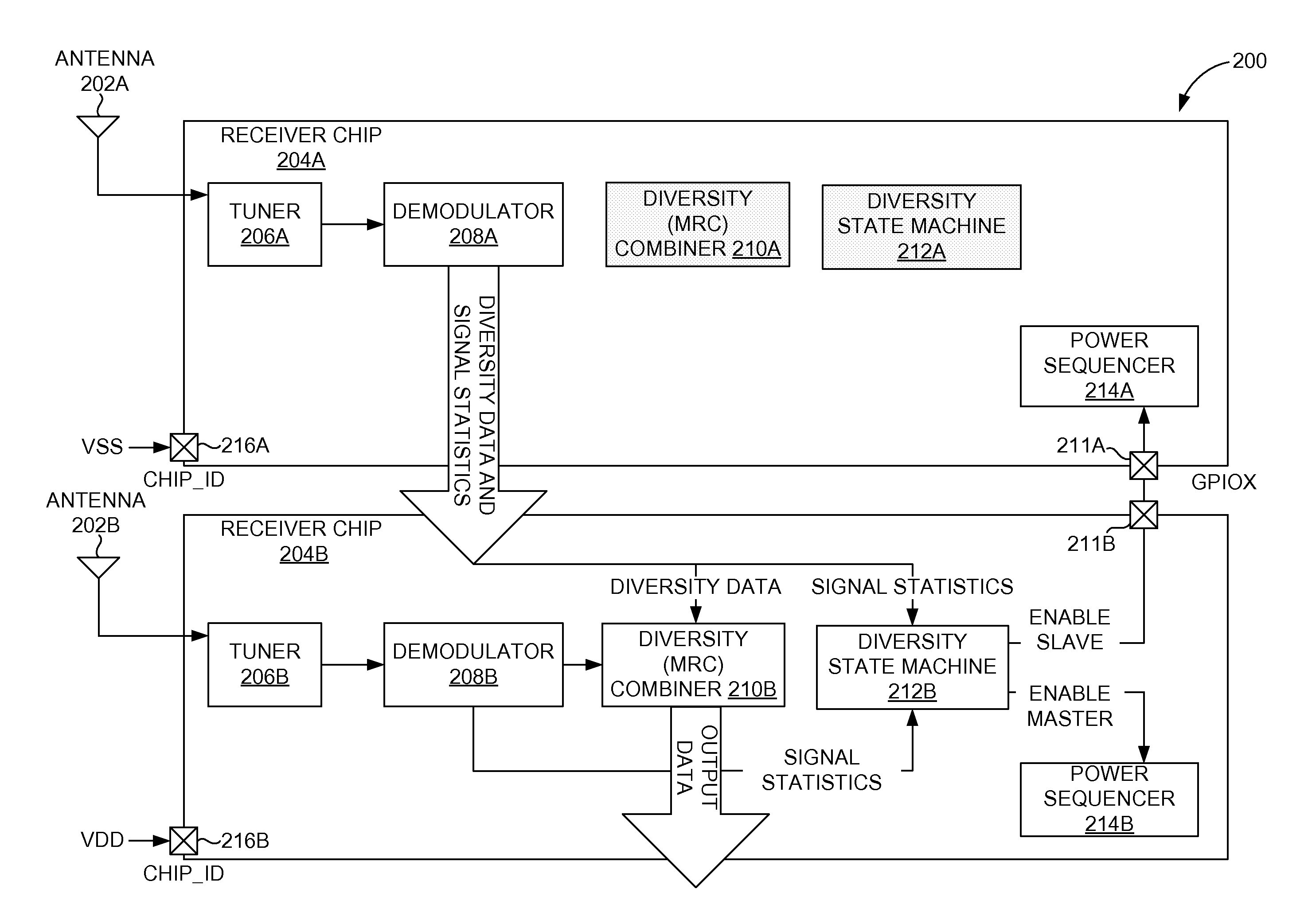
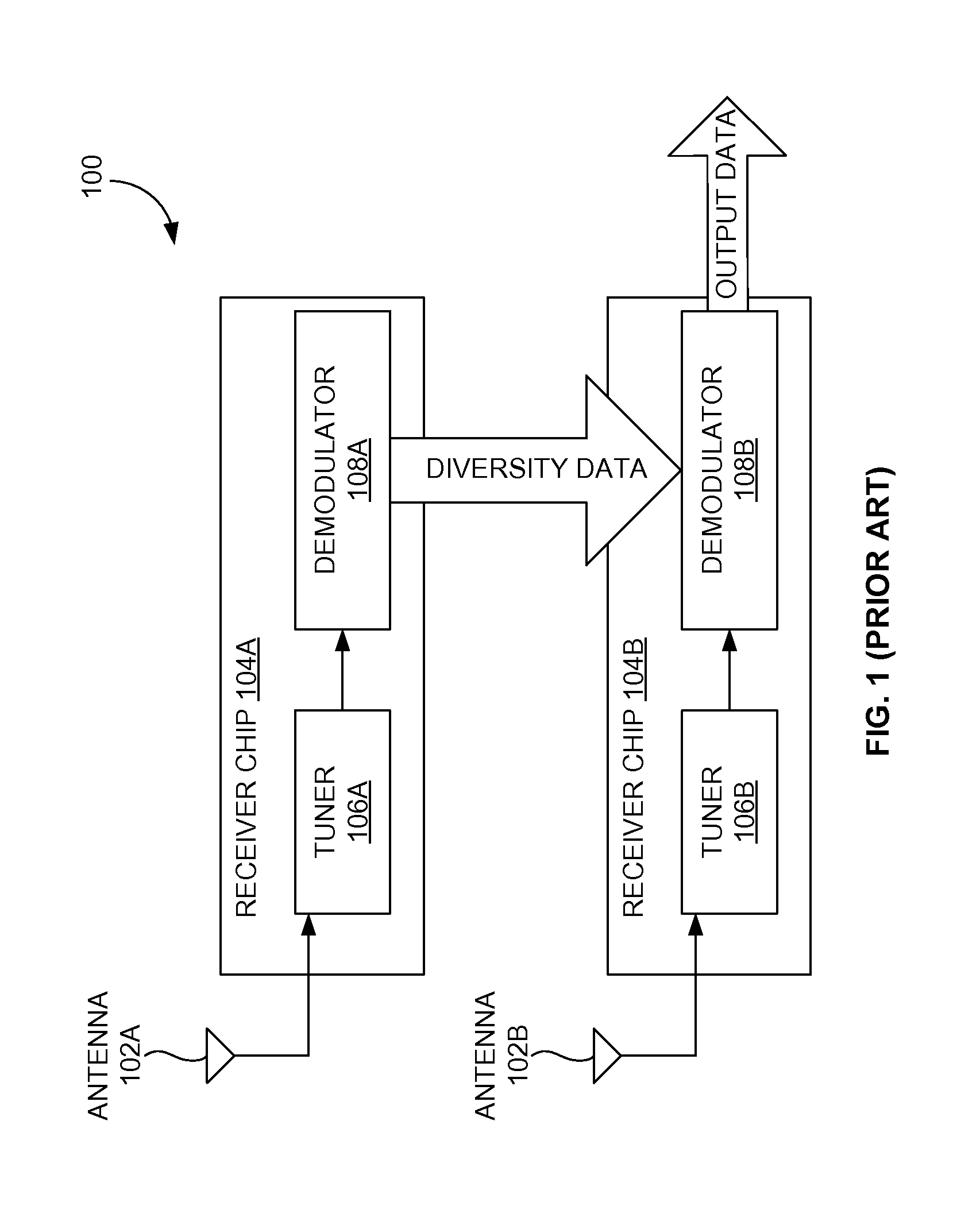
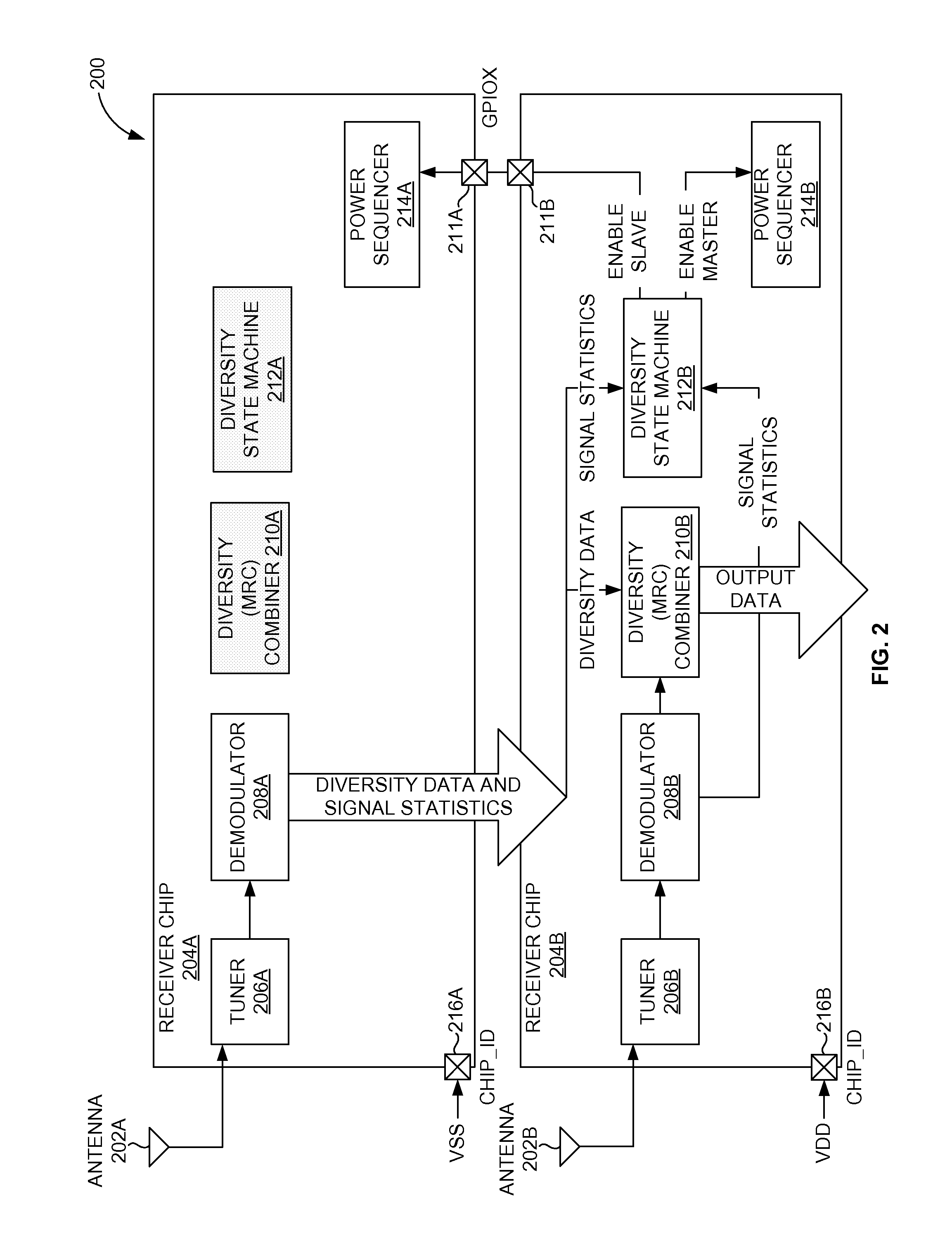
a diversity architecture and low power technology, applied in power management, amplitude demodulation, high-level techniques, etc., can solve problems such as double power consumption, and achieve the effect of removing a majority of device leakage power
- Summary
- Abstract
- Description
- Claims
- Application Information
AI Technical Summary
Benefits of technology
Problems solved by technology
Method used
Image
Examples
first embodiment
[0036]FIG. 3A illustrates a block diagram of multi-chip antenna diversity architecture 300A when both a master chip 304B and a slave chip 304A are powered ON herein. The multi-chip antenna diversity architecture 300A includes the slave chip 304A and master chip 304B. The slave chip 304A includes an antenna 302A, a clock PLL 306A, a crystal oscillator 308A, a tuner 310A, a demodulator 312A, a MRC 314A, a power sequencer 316A, and a Diversity State Machine 318A. Similarly, the master chip 304B includes an antenna 302B, a clock phase lock loop (PLL) 306B, a crystal oscillator 308B, a tuner 310B, a demodulator 312B, a MRC 314B, a power sequencer 316B, and a Diversity State Machine 318B.
[0037]The master chip 304B receives an input signal from the antenna 302B. Similarly, the slave chip 304A receives an input signal from the antenna 302A. The clock PLL 306A-B generates digital clock signals from an input signal received. The output from crystal oscillator 308B of the master chip 304B is ...
second embodiment
[0038]With reference to FIG. 3A, FIG. 3B illustrates the block diagram of the multi-chip antenna diversity architecture 300B when only the master chip 304B is powered ON herein. In one embodiment, when only the master chip 304B is powered ON, then the clock PLL 306B, the crystal oscillator 308B, the power sequencer 316A-B, and the Diversity State Machine 318A-B are powered ON. In another embodiment, the functions of the clock PLL 306A, the crystal oscillator 308A, the tuner 310A, the demodulator 312A, and the MRC 314A are disabled or powered OFF as shown in FIG. 3B. The tuner 310B, the demodulator 312B, and the MRC 314B are active.
third embodiment
[0039]With reference to FIG. 3A through FIG. 3B, FIG. 3C illustrates the block diagram of the multi-chip antenna diversity architecture 300C when only the slave chip 304A is powered ON herein. In one embodiment, when only the slave chip 304A is powered ON, then the clock PLL 306A, the crystal oscillator 308A, the power sequencer 316A-B, the MRC 314A, and the Diversity State Machine 318A-B are powered ON. In another embodiment, the functions of the crystal oscillator 308A, and the MRC 314A are disabled or powered OFF as shown in FIG. 3C. The MRC 314B, the clock PLL 306A, the tuner 310A, and the demodulator 312A are active.
[0040]If the channel conditions are adequate for a single chip (e.g., the master chip 304B, or the slave chip 304A) to receive error free audio / video data, then the DSM 318B powers down either the master chip 304B or the slave chip 304A. This occurs to allow the final audio / video data to always be transmitted from the master chip 304B. The DSM 318B determines the r...
PUM
 Abstract
Description
Claims
Application Information
 - R&D
- Intellectual Property
- Life Sciences
- Materials
- Tech Scout
- Unparalleled Data Quality
- Higher Quality Content
- 60% Fewer Hallucinations
Browse by: Latest US Patents, China's latest patents, Technical Efficacy Thesaurus, Application Domain, Technology Topic, Popular Technical Reports.
© 2025 PatSnap. All rights reserved.Legal|Privacy policy|Modern Slavery Act Transparency Statement|Sitemap|About US| Contact US: help@patsnap.com


