Automatic selective retest for multi-site testers

a multi-site tester and automatic selective technology, applied in the direction of resistance/reactance/impedence, testing circuit, instruments, etc., can solve the problems of wasting time waiting, limiting the number of devices to generally 8 devices, and not allowing for as accurate control and timing of the test program

Active Publication Date: 2010-01-19
TEXAS INSTR INC
View PDF4 Cites 2 Cited by
  • Summary
  • Abstract
  • Description
  • Claims
  • Application Information

AI Technical Summary

Benefits of technology

[0017]The actual time lost in any of the rescreen methods described above was estimated by the present Inventors using an overall equipment efficiency (OEE) model. From preliminary data, losses were estimated to be around 4% for manual re-screen and can be more than 4% for the auto-reprobe method or related variants for short test times (e.g. <5 seconds, particularly for test times <2 seconds) and high parallelism on the load boards. Embodiments of the present invention referred to herein as “automatic selective retest” can eliminate a majority of the losses and thus can provide a 2% to a 4% OEE gain which translates into significantly reduced cost / unit test cost.
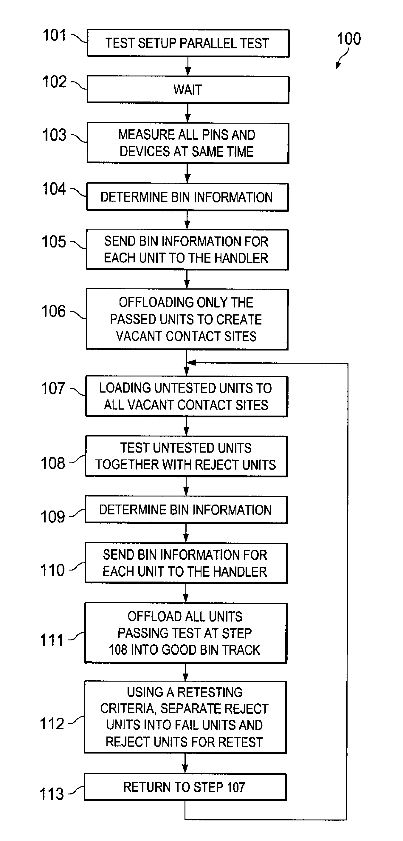
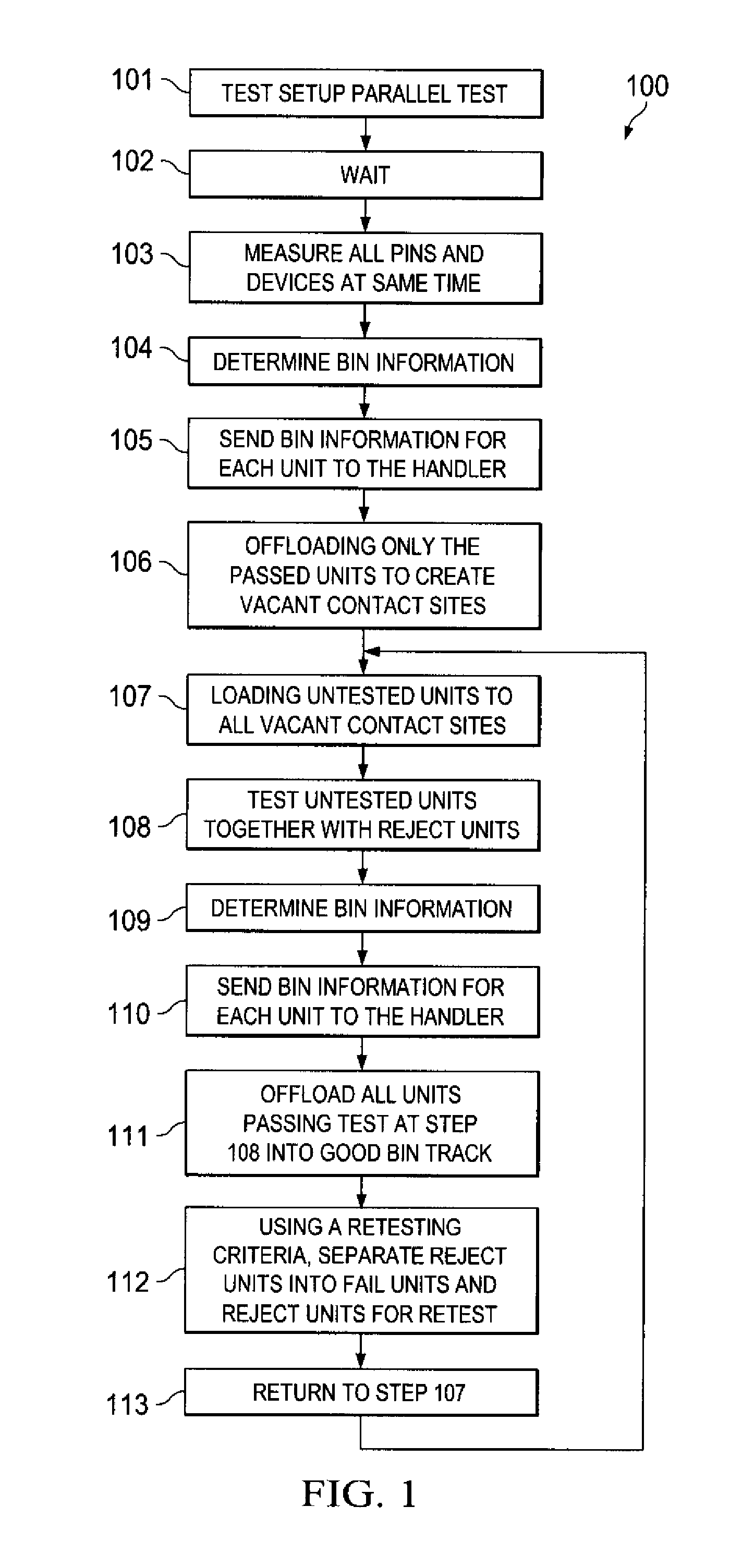
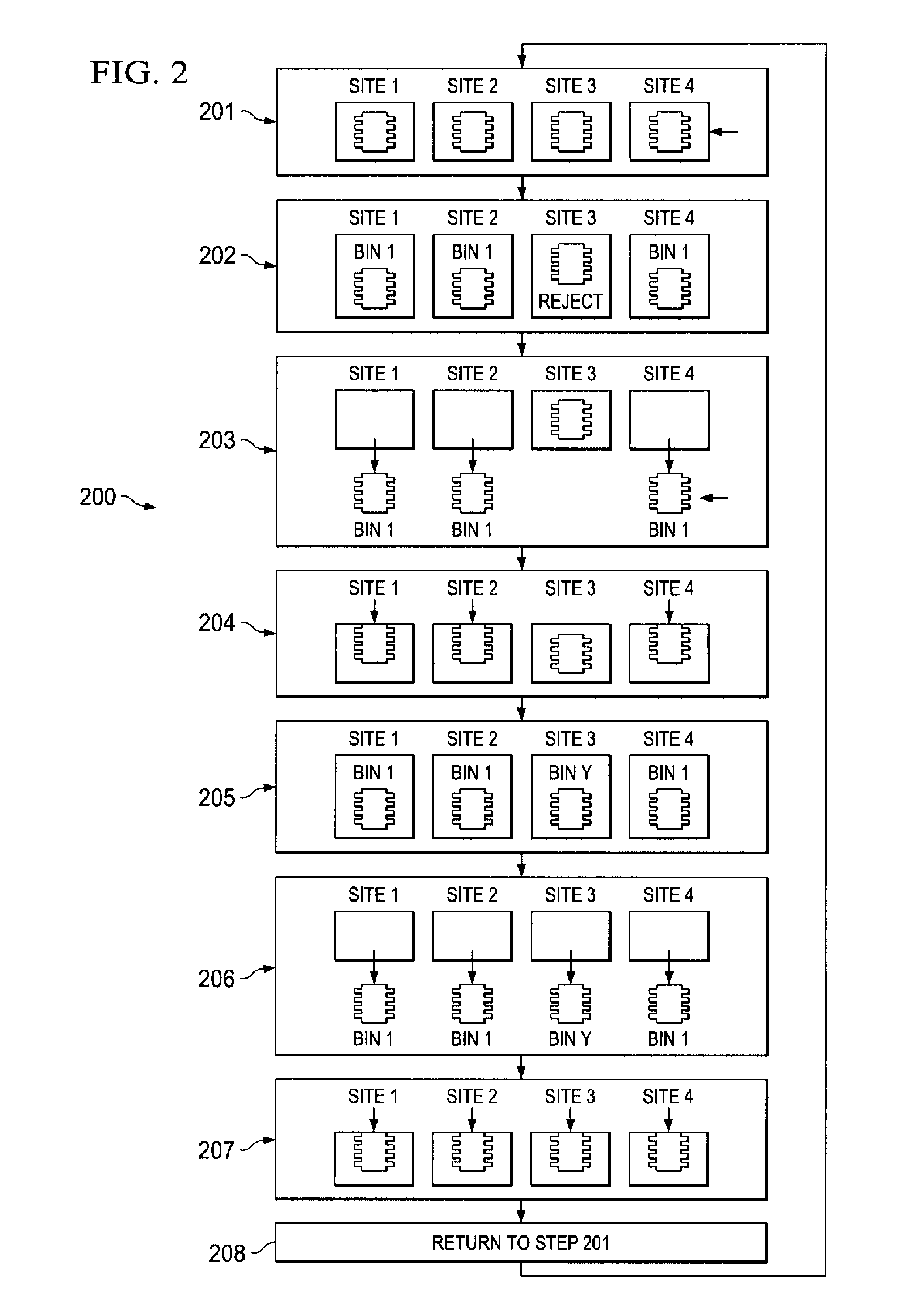
[0018]Embodiments of the present invention include a multi-site automated tester and related automatic selective retest method. Instead of unloading then loading the reject units from a batch of semiconductor units for rescreen as in a manual rescreen, the units are instead generally handled by binning and sorting only the passing (good) units to create vacant contact sites, and indexing untested units into the vacant contact sites thus replacing only the sorted good units. The reject units remain at their respective contact sites and are re-plunged and re-tested along with the untested units in the next test cycle, in contrast with conventional auto-reprobe which keeps both good and reject units at their respective contact sites and reduces tester efficiency by retesting both good and reject units.
[0021]Selective retest testing according to embodiments of the invention can recover a significant portion (e.g. at least ½) of the 4% OEE loss characteristic of conventional retesting sequencings. Embodiments according to the invention thus generally reduce total test times for the batch, increase throughput, and can also improve yields by allowing the tester to adjust to setup problems.

Problems solved by technology

The software generally allows up to 32 devices to be tested in the multi-site mode, although, for most devices, hardware limitations limit the number of devices to generally 8 devices.
Also, because dual-site testing utilizes two separate controllers, it does not allow for as accurate control and timing of the test program, compared to a test program controlled by a single controller.
The manual rescreen method generally results in wasted time waiting for:a) trailing units in the lot to be unloaded / sorted;b) the handler to determine a clean empty state;c) the operator to close the current segment (requires counting and handling of units);d) the operator to initialize a new segment for the re-screen (requires counting and handling of units in addition to other paperwork / actions);e) the operator to manually load the units into the input of the handler;f) the handler to initialize its modules coming from a stop state, andg) the handler to load the units into the contact site(s) to be tested.
Although generally effective for re-binning a percentage of reject units into good units, potentially productive test time is wasted by the required operator handling time, as well as time for the handler to index the units for retest.
The inherent problem with the auto-reprobe method is that it reduces multi-site efficiency (MSE) while trying to improve miscontact.
Specifically, good units are replunged with the bad devices.
When devices run comparatively short test times and high parallelism, the adverse affect on MSE becomes more severe.
As a result, for devices with short test times (e.g. <5 secs) and higher multi-site solutions (e.g. ≧8), auto-reprobe may result in no test efficiency improvement over the manual rescreen method.

Method used


Image

  • Automatic selective retest for multi-site testers
  • Automatic selective retest for multi-site testers
  • Automatic selective retest for multi-site testers

Examples


Embodiment Construction

[0026]The present invention is described with reference to the attached figures, wherein like reference numerals are used throughout the figures to designate similar or equivalent elements. The figures are not drawn to scale and they are provided merely to illustrate the instant invention. Several aspects of the invention are described below with reference to example applications for illustration. It should be understood that numerous specific details, relationships, and methods are set forth to provide a full understanding of the invention. One having ordinary skill in the relevant art, however, will readily recognize that the invention can be practiced without one or more of the specific details or with other methods. In other instances, well-known structures or operations are not shown in detail to avoid obscuring the invention. The present invention is not limited by the illustrated ordering of acts or events, as some acts may occur in different orders and / or concurrently with o...


PUM


Abstract

A method of multi-site testing a batch of semiconductor units using a multi-site automated tester (100). The tester (300) includes a handler (320) coupled to a contactor (330) including a first plurality of contact sites. The method includes the step of loading the first plurality of units into the first plurality of contact sites (201). The first plurality of units are simultaneously tested (202) using a test program to determine bin information for each of the first plurality of units, wherein the bin information defines each of the first plurality units as being a passed unit or a reject unit. The passed units are offloaded from respective contact sites of the first plurality of contact sites to create vacant contact sites (203), while keeping the reject unit(s) at respective contact sites of the first plurality of contact sites. Untested units from the batch are then loaded to fill the vacant contact sites (204). Simultaneously, the reject units retested and untested units are tested using the test program (205).

Description

FIELD OF INVENTION[0001]This invention relates to semiconductor chip testing and more particularly multi-site testers and testing.BACKGROUND[0002]Being able to test more than one device at a time on a given tester is a simple and effective means of lowering test time and improving throughput, provided the hardware and software allow it. There are generally two different methods for testing multiple devices simultaneously on a tester.[0003]The first method is referred to as dual-site testing. In this method, the hardware is split evenly into an X quadrant and a Y quadrant, and each quadrant is controlled by either the primary or a secondary controller. Dual site testing is basically just two test programs running simultaneously on the same TESTER, each having its own controller and hardware. Since there is only one high speed clock on the TESTER, special attention must generally be paid when using clocks to allow the two test programs to synchronize.[0004]The other method of simultan...

Claims


Application Information

Patent Timeline
Patent Type & Authority Patents(United States)
IPC IPC(8): G01R31/14G01R31/01
CPCG01R31/2894G01R31/01G01R31/2893
Inventor LEE, CHI TSUNGCHEN, SHENG PINYOU, MING CHUANHSU, SHOU PING
Owner TEXAS INSTR INC
Why Eureka
Try Eureka