Eureka AIR delivers breakthrough ideas for toughest innovation challenges, trusted by R&D personnel around the world.

Extended mobility tire with undulating sidewalls

a technology of undulating sidewalls and extended mobility tires, which is applied in the field of extended mobility tires with undulating sidewalls, can solve the problems of limiting the impact of this solution, entail considerable disadvantages in terms of rolling resistance and comfort, and detriment of everyday operation, so as to prevent total sagging of sidewalls, and reduce the effect of sagging

Inactive Publication Date: 2007-10-16
MICHELIN RECH & TECH SA
View PDF9 Cites 3 Cited by
  • Summary
  • Abstract
  • Description
  • Claims
  • Application Information

AI Technical Summary

Benefits of technology

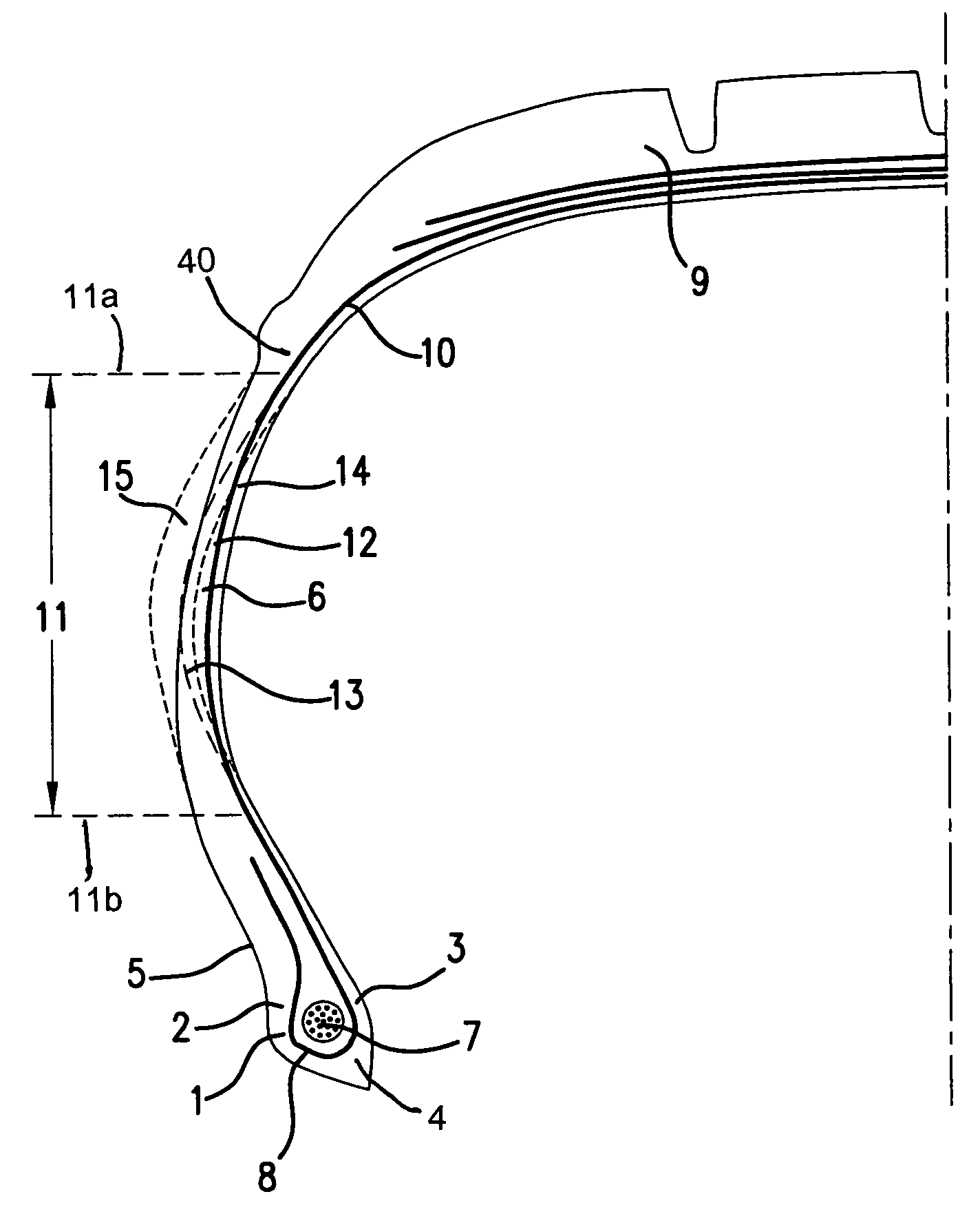
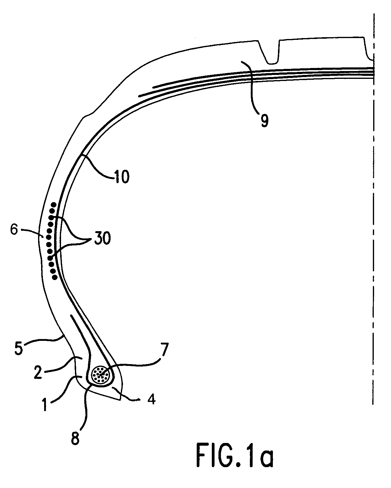
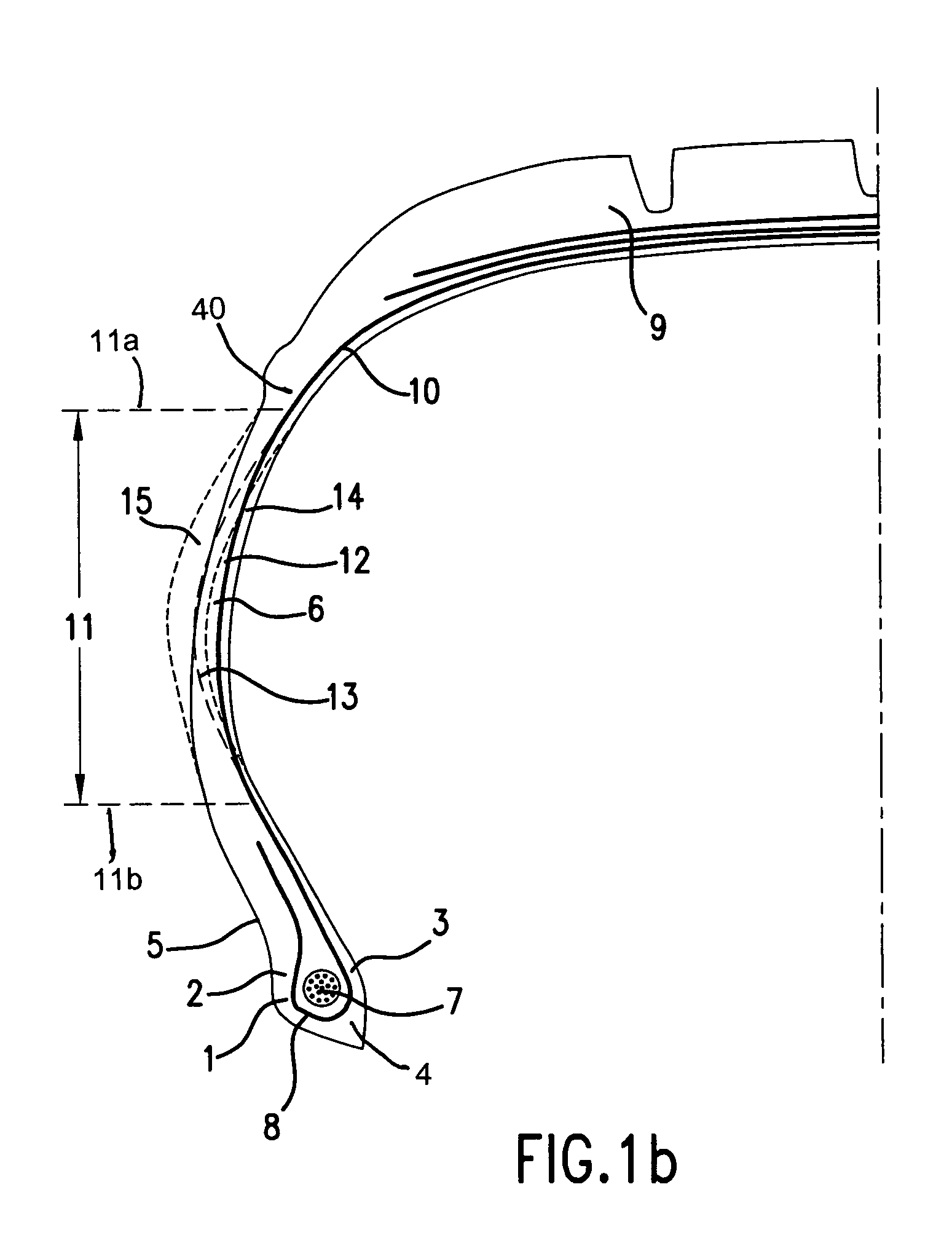
[0007]The solution proposed by the present invention makes it possible to eliminate the majority of the drawbacks associated with the current techniques allowing extended mobility. On the one hand, the tire does not require any support for travel at low pressure; on the other hand, it does not have rigid sidewalls reinforced for example by means of inserts of rubber material. The sidewalls exhibit a structural rigidity which varies with the deflection of the tire. Thus, when the tire travels at its rated pressure, the structural rigidity is that of a standard tire. The sidewalls exhibit a flexibility which is advantageously comparable to a conventional tire. Favourable characteristics such as a high level of comfort, a low rolling resistance, good endurance, etc., may be retained. The tire according to the invention thus exhibits the advantages associated with a self-supporting tire, which make it possible to ensure extended mobility, but without exhibiting the drawbacks which affect tire qualities during everyday use substantially at normal pressure.
[0009]Since, after stretching of the undulating cords in the sidewalls, buckling of the sidewalls is in some way “blocked”, considerable, or indeed total, sagging of the tire does not take place, in particular at the level of the contact area. The load is thus to a great extent borne by the tensioning of the circumferential cords. Thus, with greatly reduced or zero pressure, the tire operates with greater deflection and a considerably higher structural rigidity, not only in order to prevent total sagging of the sidewalls but also to make it possible to bear the load despite the drop in pressure, in a manner comparable to a self-supporting tire.

Problems solved by technology

Reinforced sidewall technologies favour operation in degraded mode, normally exceptional or at the very least very occasional for the vast majority of vehicles, to the detriment of everyday operation, which suffers the drawbacks intrinsic to the principle of reinforced sidewalls.
In normal operation, at rated service pressure, this may entail considerable disadvantages in terms of rolling resistance and comfort.
Furthermore, the strong tendency for the bottom zone of the tire to want to slide out of the rim under the effect of sidewall sagging may limit the impact of this solution.
On the other hand, it exhibits the drawback of requiring an additional component, the support, for each of the wheels of the vehicle.

Method used


Image

  • Extended mobility tire with undulating sidewalls
  • Extended mobility tire with undulating sidewalls
  • Extended mobility tire with undulating sidewalls

Examples


Embodiment Construction

[0028]Tire reinforcement armatures or tire reinforcements are currently—and most frequently—formed by stacking one or more plies conventionally designated “carcass plies”, “crown plies”, etc. This way of designating reinforcement armatures stems from the manufacturing process, which consists of making a series of semi-finished products in the form of plies, provided with, often longitudinal, cord reinforcements, which are then assembled or stacked so as to build a tire blank. The plies are made flat, with large dimensions, and are then cut as a function of the dimensions of a given product. The plies are also assembled substantially flat in a first phase. The blank thus produced is then shaped into the toroidal profile typical of tires. The semi-finished products known as “finishing products” are then applied to the blank, in order to obtain a product which is ready for vulcanisation.

[0029]Such a “conventional” type of process involves, in particular for the tire blank manufacturing...


PUM


Abstract

A tire includes at least one carcass-type reinforcement structure anchored on each side in a bead, each bead being extended radially towards the outside by a sidewall having at least one substantially resilient circumferential cord disposed in the substantially median portion of the sidewalls. The carcass-type reinforcement structure includes a ply of carcass cords extending from the bead to the crown within a sidewall. The carcass cords are arranged in such a way that, in a sidewall zone restricted to the median portion of the sidewall, the carcass cords exhibit different respective axial positions, so as to form around the circumference a succession of substantially regular undulations defining an undulating circumferential profile. Outside of the sidewall zone, the carcass cords of the ply do not form undulations. At reduced pressure the undulations tend to straighten out and rigidify the sidewall in such a way as to be able to bear the load.

Description

[0001]This application is a continuation of International Application Serial No. PCT / EP03 / 12499 filed on Nov. 10, 2003, and which published on Jun. 3, 2004 under Publication No. WO 2004 / 045879.BACKGROUND[0002]The present invention relates to tires. More particularly, it relates to a tire comprising a specific arrangement of the cords of the carcass-type reinforcement structure in the sidewalls, allowing the obtainment, on the one hand, under substantially normal pressure, of flexible sidewalls capable of imparting particularly favourable qualities, in particular of comfort and rolling resistance, and, on the other hand, under reduced pressure, of rigidified sidewalls capable of bearing the load on the tire, within certain limits.[0003]For some years, tire manufacturers have been devoting considerable effort to developing original solutions to a problem dating back to the very first time use was made of wheels fitted with tires of the inflated type, namely how to allow the vehicle to...

Claims


Application Information

Patent Timeline
Patent Type & Authority Patents(United States)
IPC IPC(8): B60C17/00B60C13/02B60C17/08B60C3/00B60C9/02B60C9/08B60C9/09B60C13/00
CPCB60C9/09Y10T152/10864B60C9/08
Inventor MERINO LOPEZ, JOSE
Owner MICHELIN RECH & TECH SA
Why Eureka
Eureka Blog
Learn More