Occipital plate

a technology of occipital plate and occipital plateau, which is applied in the field of occipital plate, can solve the problems of long preparation time, difficult use form, and difficult connection of implants to longitudinal rod members and occipital plateau without stressing atlantoaxial joints

Inactive Publication Date: 2013-09-26
MACKALL JOHN L
View PDF14 Cites 14 Cited by
  • Summary
  • Abstract
  • Description
  • Claims
  • Application Information

AI Technical Summary

Problems solved by technology

The most simple, but generally most difficult, to use form is that of a rod that smoothly tapers to an occipital plate that must be bent and contoured to match highly varied anatomy.
All of these iterations have at most one to two degrees of freedom and typically require long preparation time to ensure a proper bend.
This makes the implants both difficult to connect to the longitudinal rod member and the occipital plateau without putting stress on the atlantoaxial joint.

Method used


Image

  • Occipital plate
  • Occipital plate
  • Occipital plate

Examples


Embodiment Construction

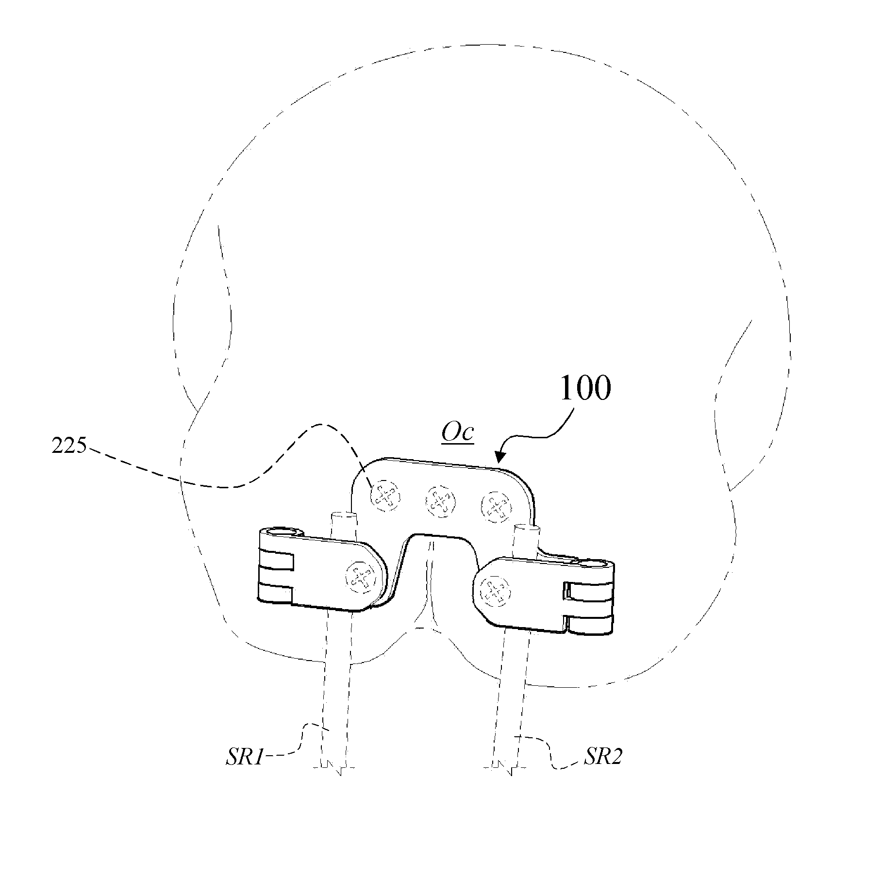
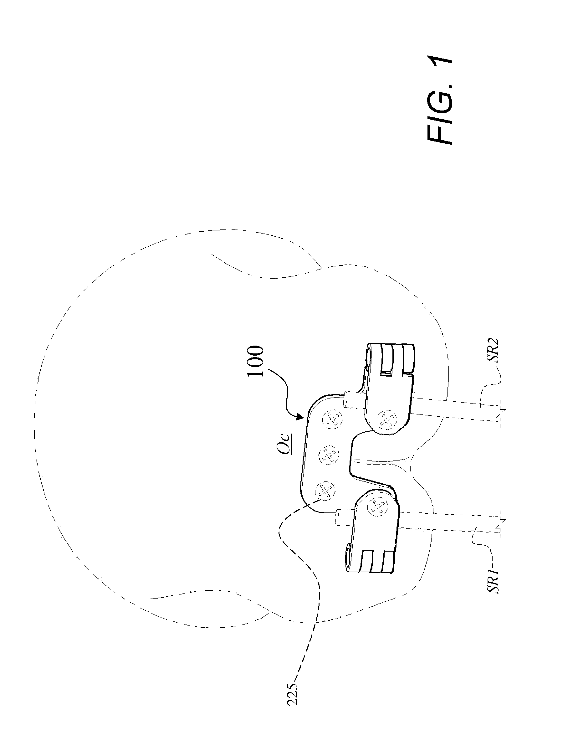
[0020]This invention relates to medical devices. More specifically, the invention is directed to an occipital plate 100 for use in an occipitocervical fixation procedure. The occipital plate 100 and its parts can be made out of any suitable material such as, but not limited to, titanium, tungsten, and stainless steel, alone or in combination. Part numbers are listed in Table 1 (shown in FIG. 16).

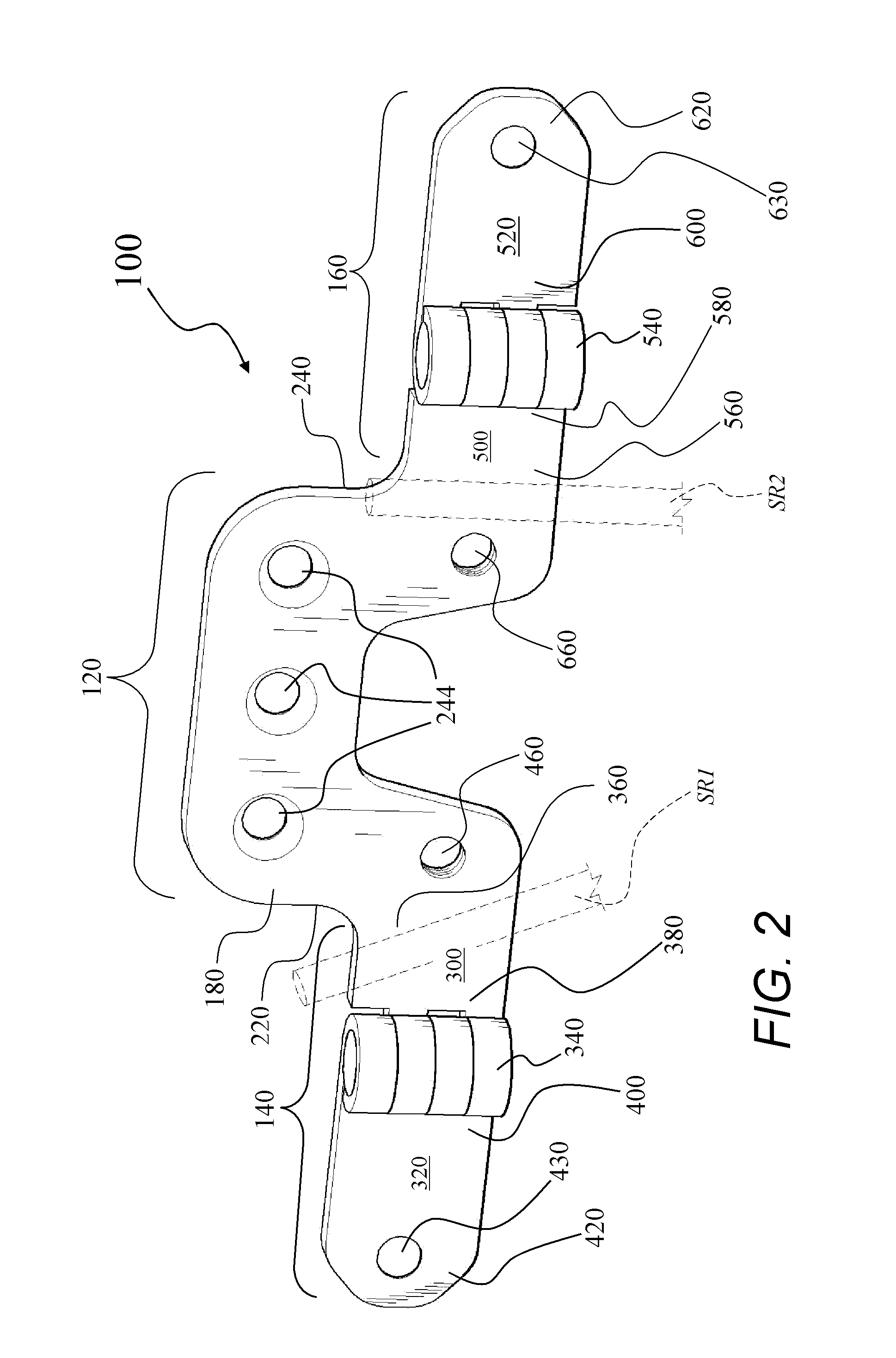
[0021]The occipital plate 100 comprises a middle portion 120, a left hinged leg 140, and a right hinged leg 160. The occipital plate 100 defines a central axis line 130. While not necessary it is preferred that the occipital plate 100 exhibits 2-fold symmetry about central axis line 130. The middle portion 120 defines front 180 and rear 200 surfaces, and left 220 and right 240 opposite sides. Holes 244 extend from the front surface 180 through to the rear surface 200 of the middle portion 120 are provided for receiving bone fasteners 225 for fixation of occipital plate 100 to the occiput Oc,...


PUM


Abstract

An occipital plate for use in an occipitocervical fixation procedure to stabilize the base of a patient's skull with respect to the patient's neck. The occipital plate of the invention is made up of a middle portion having left and right sides, and left and right hinged legs extending outward in opposite directions from the left and right sides of the middle portion. Each of the left and right hinged legs uses a hinge mechanism to secure a spinal rod to the occipital plate.

Description

CROSS-REFERENCE TO RELATED APPLICATIONS[0001]Not Applicable.STATEMENT REGARDING FEDERALLY SPONSORED RESEARCH OR DEVELOPMENT[0002]Not Applicable.FIELD OF THE INVENTION[0003]This invention relates to medical devices. More specifically, the invention is directed to an occipital plate.BACKGROUND OF THE INVENTION[0004]As noted in U.S. Pat. No. 7,695,500 issued to Markworth, there are many occipital plate implants on the market today. Some implants have through-holes and must be preloaded on the rod. Others have top loading sockets similar to polyaxial screws which allow bent rods to be anchored to the plate. The most simple, but generally most difficult, to use form is that of a rod that smoothly tapers to an occipital plate that must be bent and contoured to match highly varied anatomy. All of these iterations have at most one to two degrees of freedom and typically require long preparation time to ensure a proper bend. This makes the implants both difficult to connect to the longitudin...

Claims


Application Information

Patent Timeline
Patent Type & Authority Applications(United States)
IPC IPC(8): A61B17/80
CPCA61B17/7059A61B17/7055
Inventor MACKALL, JOHN L
Owner MACKALL JOHN L
Why Eureka
Try Eureka