
Lens System for Lighting Fixture

a technology of lens system and lighting fixture, applied in the field of lens system, can solve the problems of filament light source losing all utility, and filament based lamp lighting providing only one source of ligh

Inactive Publication Date: 2013-10-10
JST PERFORMANCE
View PDF18 Cites 47 Cited by
  • Summary
  • Abstract
  • Description
  • Claims
  • Application Information

AI Technical Summary

Benefits of technology

The invention is a lens system that can be used in a variety of lighting fixtures. It includes one or more insertable lenses that can be removed or replaced to create different lighting effects. The lenses are securely attached to a protective transparent media that is attached to the fixture. The lenses have a design that fits snugly on the media to prevent movement. This design also allows the lenses to be easily replaced with different lenses to achieve different lighting effects. Overall, the invention provides a versatile and customizable solution for creating custom lighting effects.

Problems solved by technology

Filament based lamp lighting has inherent drawbacks.
Second, filament lighting provides but one source of light.
If the bulb ruptures or filament expires, the light source loses all utility.
The use of LEDs however also presents challenges related to directing or distributing generated light.
One challenge is the relative brightness of a typical single LED, which is significantly less than a capable filament based bulb and less than required for a vehicle lamp.

Method used


Image

  • Lens System for Lighting Fixture
  • Lens System for Lighting Fixture
  • Lens System for Lighting Fixture

Examples


Embodiment Construction

[0019]The embodiments of the invention are described by reference to the illustrations or drawings of embodiments that incorporate aspects or objects of the invention. The embodiments are intended to illustrate aspects of the invention but are not to be read to impose unexpressed or implied limitations on the claimed invention.

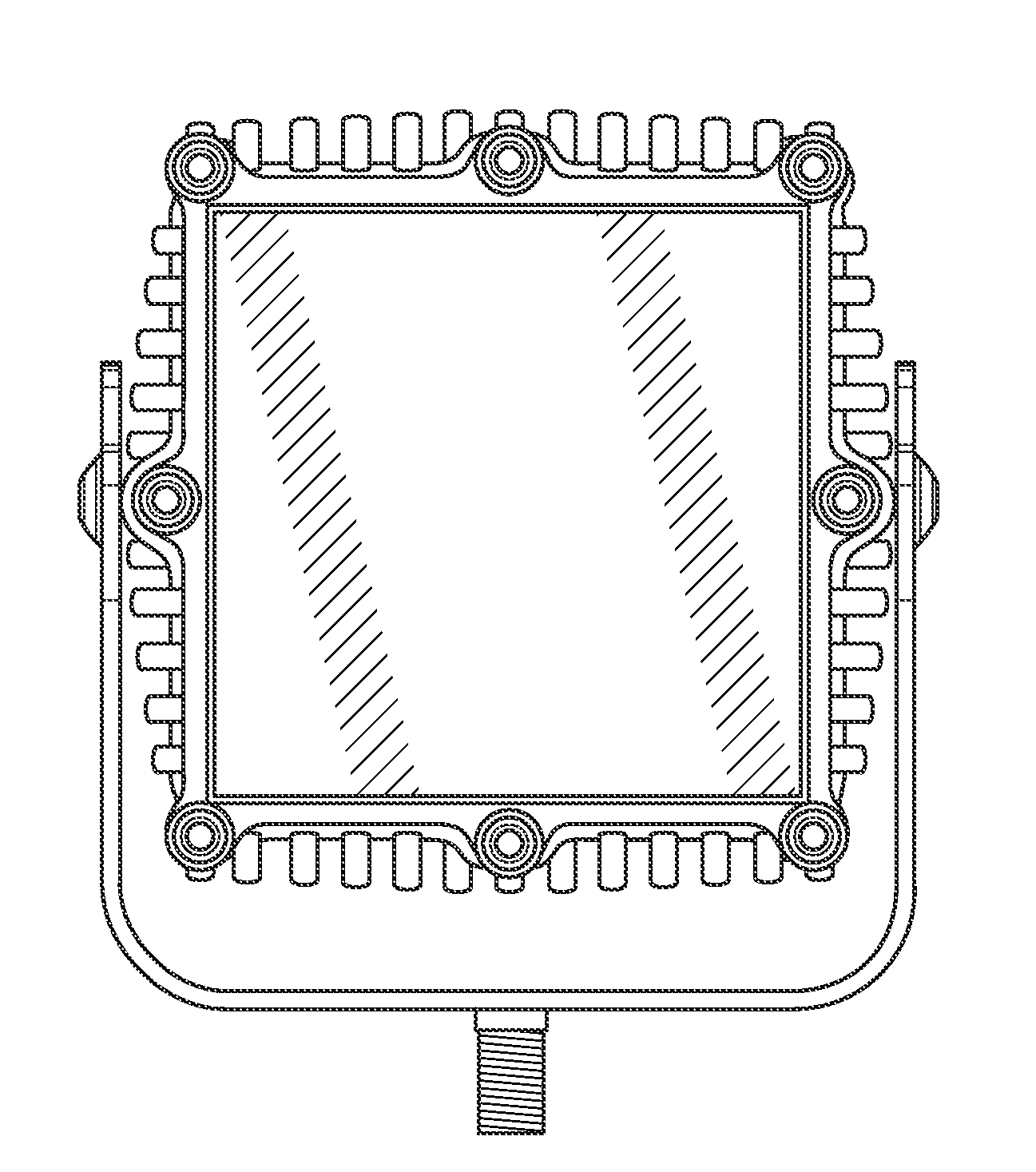
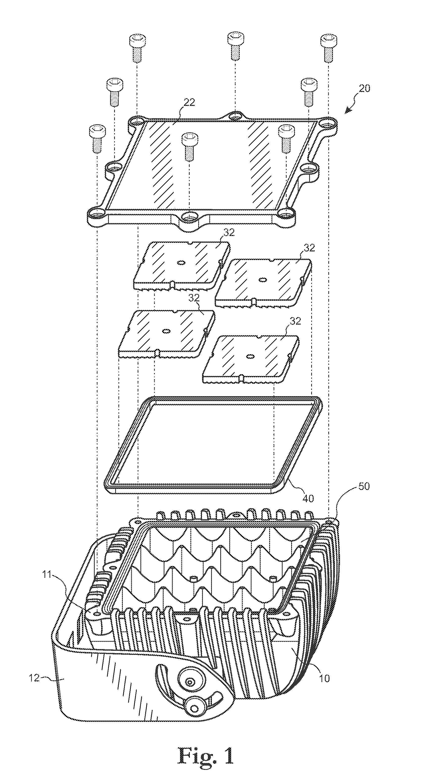
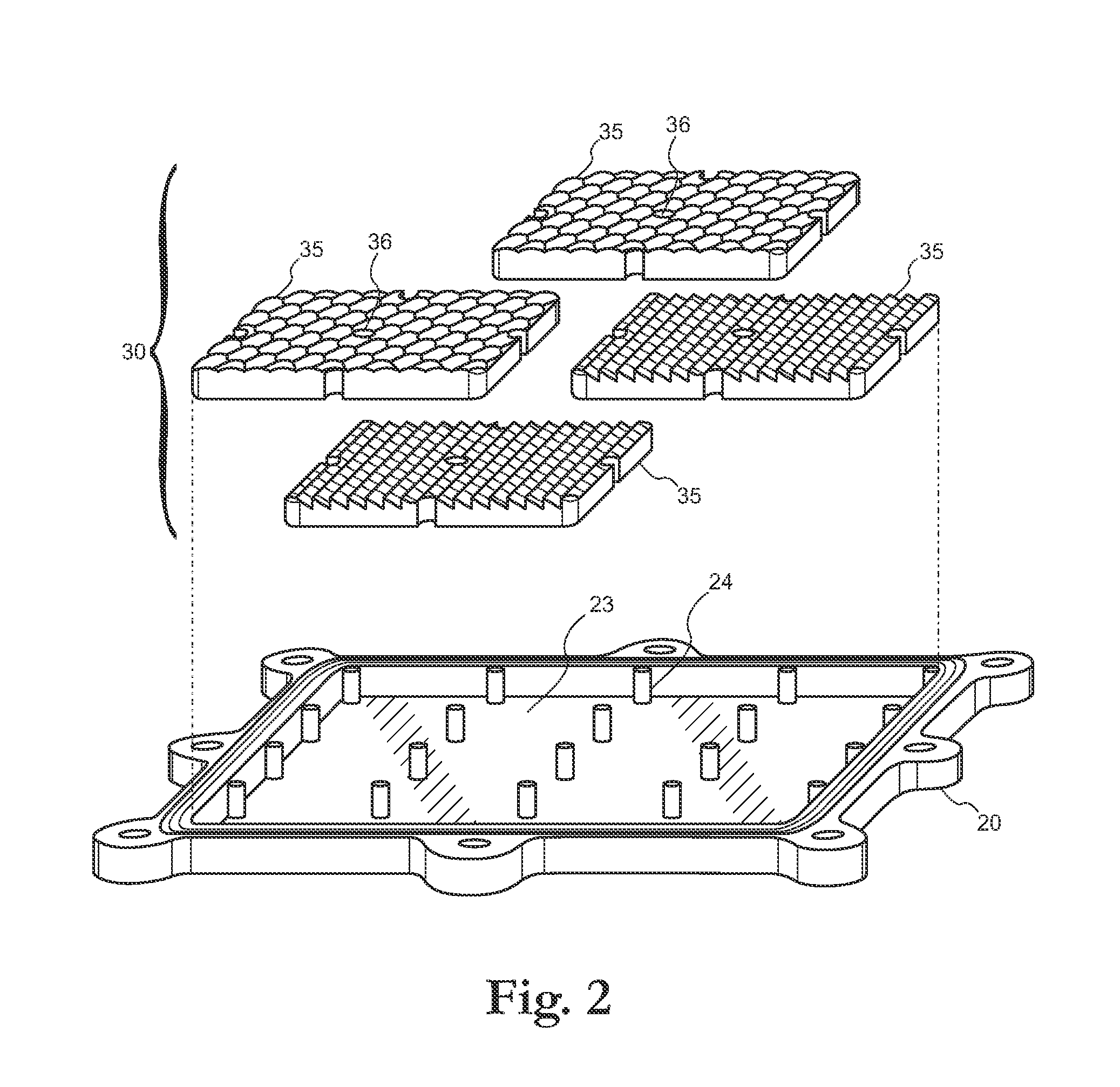
[0020]FIG. 1 illustrates an exploded side perspective showing the components of the lens system for a preferred lighting enclosure including aspects of the invention. The lighting enclosure includes a body 10 comprising a concave structure having at least a rear wall and a side-wall 11 having a side-wall perimeter edge. The rear wall comprises an inner and protected mounting surface 13 for the power circuitry and circuit boards upon which light sources such as LEDs and associated circuitry is mounted. Further, while FIG. 1. illustrates a square lighting fixture, the invention can be embodied in any size or shape lighting fixture including lighting fixtures hav...


PUM


Abstract

A lens system including one or more insertable lenses that are secured from movement relative to a protective transparent media that itself is securable to a lighting enclosure with a light source in the lighting enclosure. The insertable lenses can be removable or alternately oriented to alter the distribution of light or the projection direction of light, respectively.

Description

BACKGROUND OF THE INVENTION[0001]1. Field of the Invention[0002]The present invention relates to lens systems for refracting and distributing emitted light and particularly relates to lens systems allowing change in the refraction and distribution characteristic of light emitted from a lighting fixture.[0003]2. Discussion of the Prior Art[0004]Exterior vehicle lighting including the efficient generation, distribution, or direction of lighting facilitates both the ability for the driver to see, and for the vehicle to be seen, in low ambient light conditions. Selection or design of vehicle lighting component including without limitation, the light source, reflector(s), and lens, controls the ability to direct and distribute light. Filament lighting is an appropriate light source in some applications, but alternate light sources, including Light Emitting Diodes (LEDs), also find favor in certain applications of vehicle lighting systems as LEDs present advantages over filament based lam...

Claims


Application Information

Patent Timeline
IPC IPC(8): F21V5/04F21W107/10F21W107/20
CPCF21V5/04F21V29/507B60Q1/068F21S48/1154F21S48/1208F21S48/1275F21S48/1291F21S48/33F21V5/004F21V5/007F21V17/002F21V21/30F21W2101/02F21W2101/04F21Y2101/02F21Y2105/001B60Q1/0483F21Y2105/10F21Y2115/10F21S41/143F21S41/29F21S41/265F21S41/27F21S45/50F21W2107/10F21W2107/20F21S41/153
Inventor ADAMS, STEPHEN P.
Owner JST PERFORMANCE
Learn More