Implantable medical devices, and methods of use therewith, that detect exposure to magnetic fields from MRI systems

a technology of magnetic field and medical device, applied in the field of implantable medical device, can solve the problems of not providing appropriate anti-tachycardia pacing (atp) or defibrillation shock therapy, magnetic field may interfere with the operation of the imds, and cardiac signal over- or under-sensing,

Active Publication Date: 2013-10-10
PACESETTER INC
View PDF3 Cites 17 Cited by
  • Summary
  • Abstract
  • Description
  • Claims
  • Application Information

AI Technical Summary

Benefits of technology

[0011]In accordance with specific embodiments, performance of the aforementioned steps are triggered when an implantable GMR sensor, reed switch or Hall effect sensor of the IMD detects a magnetic field.
[0012]In certain embodiments, the output of the implantable sensor configured to detect acceleration, sound and/or vibration (but not a magnetic field) can be used to confirm or reject the determination, using an implantable static magnetic field detector sensor (e.g., a Hall effect sensor), that the IMD is being exposed to a magnetic field from an MRI system. In certain embodiments, the output of the implantable sensor configured to detect acceleration, sound and/or vibration (but not a magnetic field) can be used to distinguish between the IMD being exposed to a

Problems solved by technology

When IMDs are exposed to external magnetic fields, such as those produced by magnetic resonance imaging (MRI) systems, the magnetic fields may interfere with operation of the IMDs.
These forces may induce electric charges or potentials on the leads and electrodes, which can cause over- or under-sensing of cardiac signals.
This may cause the IMD to falsely detect tachycardias (which do not actually exist), potentially causing the IMD to delivery anti-tachycardia pacing (ATP) or defibrillation shock therapy (when not actually necessary).
In another example, the charges induced by MRI systems may induce sufficient noise in cardiac signals such that cardiac signals that are representative of cardiac events go undetected by an IMD.
This may cause the IMD to not detect a tachycardia (which actually exists), potentially causing the ND to not delivery appropriate anti-tachycardia pacing (ATP) or defibrillation shock therapy (when actually necessary).
This may also cause the IMD to not deliver pacing therapy since it falsely believes there are intrinsic cardiac events ongoing.
However, the need for this special external programmer and for clinician training on using the external programmer are time consuming, costly and cumbersome.
Further, this protocol may not be properly followed, e.g., in emergency situations, when the technician operating the MRI system is not aware that the patient has an IMD, and/or when an appropriate external programmer is unavailable.
An IMD's failure to switch from its normal operational mode into an MRI safe mode, when it should have, may cause the IMD to inhibit necessary pacing, or delivery unnecessarily high voltage therapy or anti-tachycardia pacing, which may induce an arrhythmia.
Further, failure of an IM

Method used


Image

  • Implantable medical devices, and methods of use therewith, that detect exposure to magnetic fields from MRI systems
  • Implantable medical devices, and methods of use therewith, that detect exposure to magnetic fields from MRI systems
  • Implantable medical devices, and methods of use therewith, that detect exposure to magnetic fields from MRI systems

Examples


Embodiment Construction

[0023]The following description is of the best modes presently contemplated for practicing various embodiments of the present invention. The description is not to be taken in a limiting sense but is made merely for the purpose of describing the general principles of the invention. The scope of the invention should be ascertained with reference to the claims. In the description of the invention that follows, like numerals or reference designators will be used to refer to like parts or elements throughout. In addition, the first digit of a reference number identifies the drawing in which the reference number first appears.

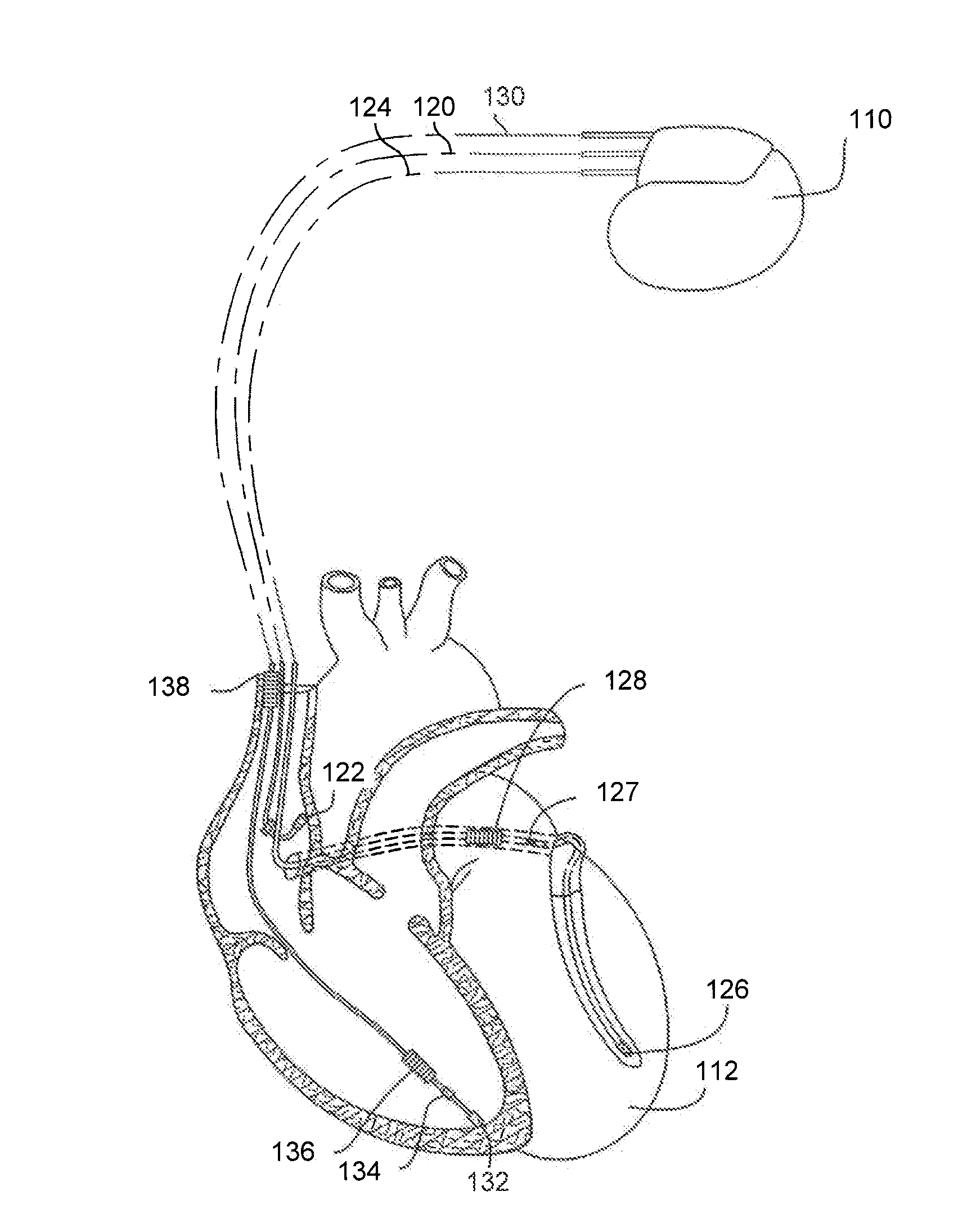
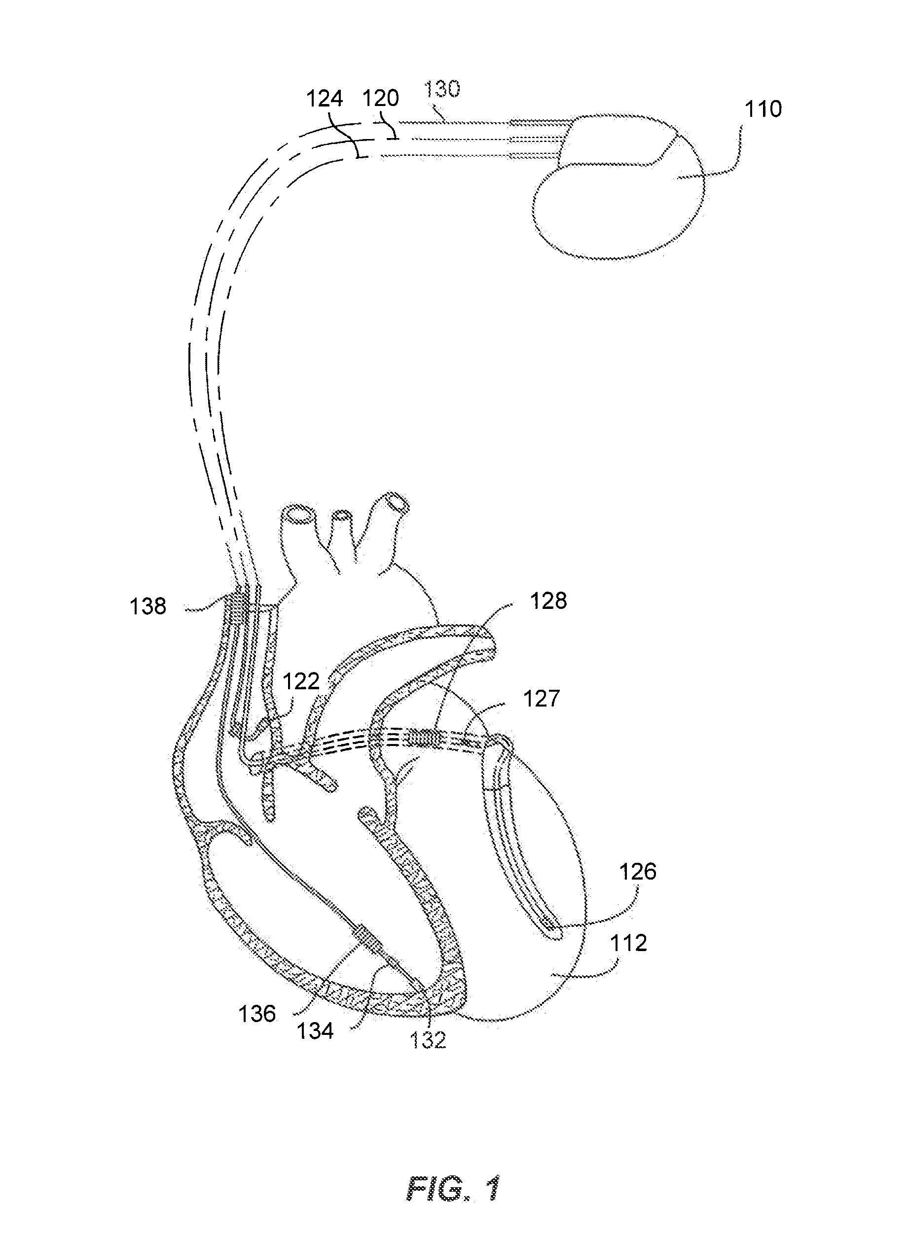
[0024]The disclosed embodiments of the present invention generally pertain to IMDs, and methods for use therewith, that detect exposure to time-varying gradient magnetic fields produced by MRI systems. Accordingly, an exemplary IMD in which embodiments of the present invention are useful is first described with reference to FIGS. 1 and 2. However, it should be noted ...


PUM


Abstract

Embodiments of the present invention generally pertain to implantable medical devices, and methods for use therewith, that detect exposure to magnetic fields produced by magnetic resonance imaging (MRI) systems. In accordance with specific embodiments, a sensor output is produced using an implantable sensor that is configured to detect acceleration, sound and/or vibration, but is not configured to detect a magnetic field. Such a sensor can be an accelerometer sensor, a strain gauge sensor or a microphone sensor, but is not limited thereto. In dependence on the produced sensor output, there is a determination whether of whether the IMD is being exposed to a time-varying gradient magnetic field from an MRI system. In accordance with certain embodiments, when there is a determination that the IMD is being exposed to a time-varying gradient magnetic field from an MRI system, then a mode switch to an MRI safe mode is performed.

Description

FIELD OF THE INVENTION[0001]Embodiments of the present invention generally pertain to implantable medical devices, and methods for use therewith, that detect exposure to magnetic fields produced by magnetic resonance imaging (MRI) systems.BACKGROUND OF THE INVENTION[0002]Implantable medical devices (IMDs) are implanted in patients to monitor, among other things, electrical cardiac activity, and to deliver appropriate cardiac electrical therapy, as required. IMDs include pacemakers, cardioverters, defibrillators, implantable cardioverter defibrillators (ICD), and the like. The electrical therapy produced by an IMD may include pacing pulses, cardioverting pulses, and / or defibrillator pulses to reverse arrhythmias (e.g., tachycardias and bradycardias) or to stimulate the contraction of cardiac tissue (e.g., cardiac pacing) to return the heart to its normal sinus rhythm. IMDs can also be used to perform cardiac resynchronization therapy (CRT).[0003]When IMDs are exposed to external magn...

Claims


Application Information

Patent Timeline
IPC IPC(8): A61N1/362A61N1/39A61N1/36
CPCA61N1/36578A61N1/3718
Inventor SISON, SHILOH
Owner PACESETTER INC
Why Eureka
Try Eureka