Proximity switch assembly and calibration method therefor

a technology of proximity switch and assembly method, which is applied in the field ofproximity switch, can solve the problems of limited ability of the driver of the vehicle to view the switch and adverse effects of capacitive switch

Active Publication Date: 2013-10-17
FORD GLOBAL TECH LLC
View PDF3 Cites 52 Cited by
  • Summary
  • Abstract
  • Description
  • Claims
  • Application Information

AI Technical Summary

Benefits of technology

[0008]According to another aspect of the present invention, a proximity switch assembly is provided. The proximity switch assembly includes a proximity sensor providing an activation field. The proximity switch assembly also includes control circuitry monitoring a signal responsive to the activation signal, determining when the signal exceeds a threshold for a time period, and calibrating the signal when the maximum signal exceeds the threshold for the time period and reaches a peak value.
[0009]According to a further aspect of the present invention, a proximity switch assembly is provided. The proximity switch assembly includes a plurality of proximity switches each including a proximity sensor providing an activation field. The proximity switch assembly includes control circuitry processing the activation field of each proximity switch to sense activation. The control circuitry monitors signals responsive to the activation fields, determines when a maximum signal exceeds a threshold for a time period, and calibrates the signals when the maximum signal exceeds the threshold for the time period and reaches a peak value.

Problems solved by technology

In some applications, such as use in an automobile, the driver of the vehicle has limited ability to view the switches due to driver distraction.
Capacitive switches can be adversely affected by condensation.

Method used


Image

  • Proximity switch assembly and calibration method therefor
  • Proximity switch assembly and calibration method therefor
  • Proximity switch assembly and calibration method therefor

Examples


Embodiment Construction

[0039]As required, detailed embodiments of the present invention are disclosed herein; however, it is to be understood that the disclosed embodiments are merely exemplary of the invention that may be embodied in various and alternative forms. The figures are not necessarily to a detailed design; some schematics may be exaggerated or minimized to show function overview. Therefore, specific structural and functional details disclosed herein are not to be interpreted as limiting, but merely as a representative basis for teaching one skilled in the art to variously employ the present invention.

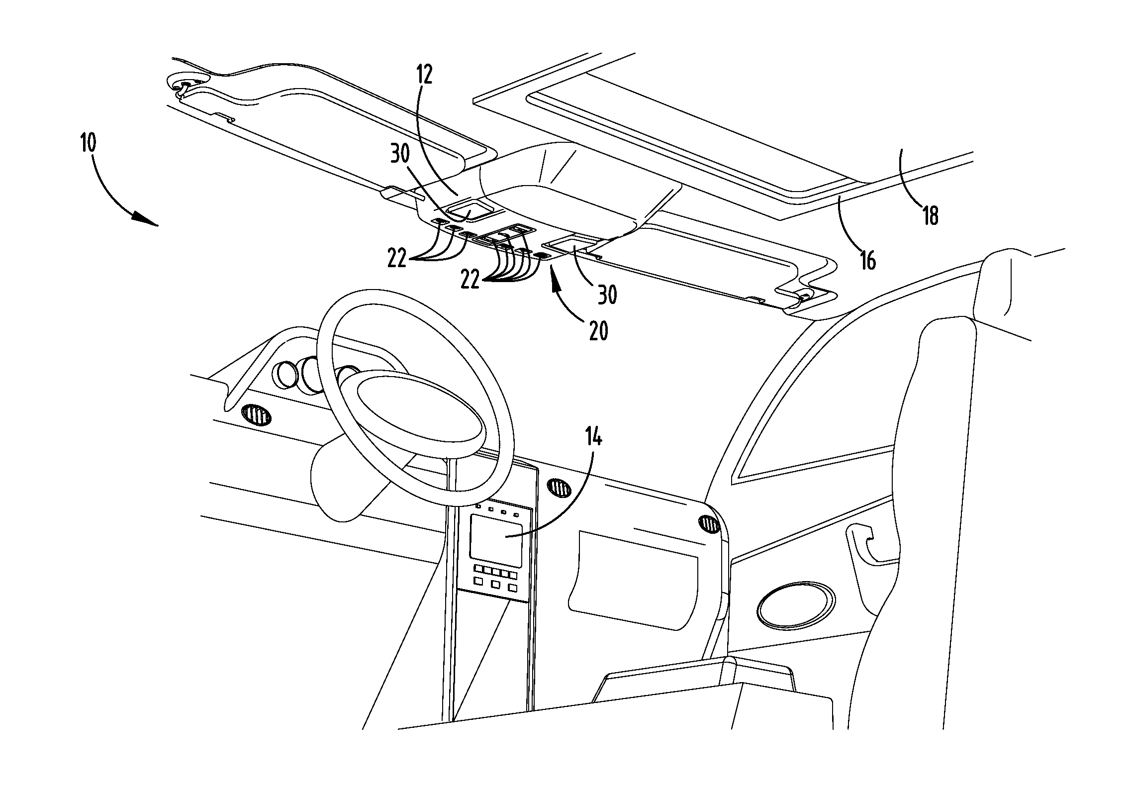
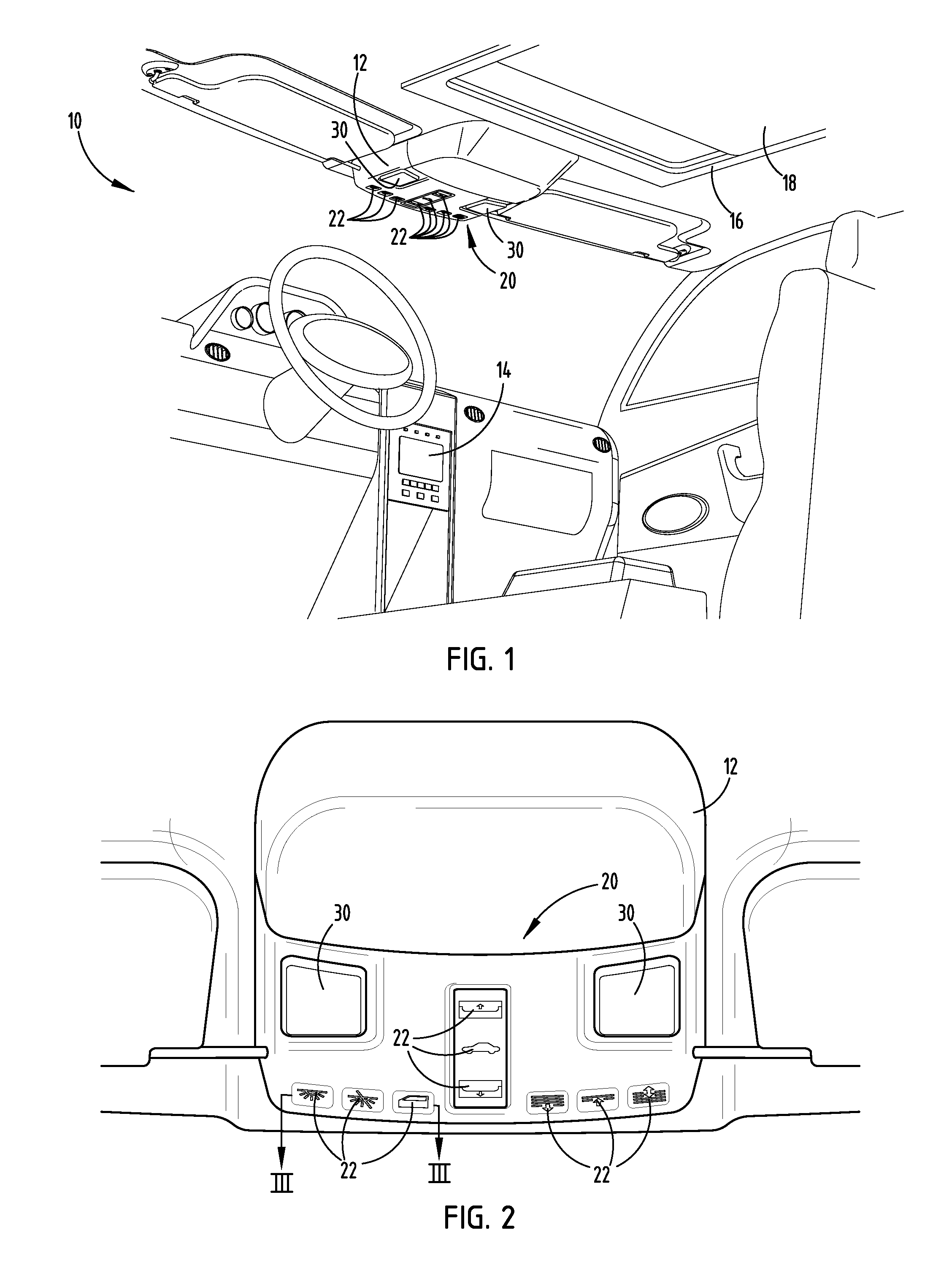
[0040]Referring to FIGS. 1 and 2, the interior of an automotive vehicle 10 is generally illustrated having a passenger compartment and a switch assembly 20 employing a plurality of proximity switches 22 having switch activation monitoring and determination and switch calibration, according to one embodiment. The vehicle 10 generally includes an overhead console 12 assembled to the headliner on the...


PUM


Abstract

A proximity switch assembly and method for detecting activation of a proximity switch assembly and calibrating the switch assembly. The assembly includes proximity switches each having a proximity sensor providing a sense activation field and control circuitry processing the activation field to sense activation. The control circuitry generates an activation output when a differential change in the signal exceeds a threshold and distinguishes an activation from an exploration of the plurality of switches. The control circuit further determines a rate of change and generates an output when the rate of change exceeds a threshold rate to enable activation of a switch and performs a calibration of the signals to reduce effects caused by changes in condensation.

Description

CROSS-REFERENCE TO RELATED APPLICATIONS[0001]This application is a continuation-in-part of U.S. patent application Ser. No. 13 / 721,886, filed on Dec. 20, 2012, entitled “PROXIMITY SWITCH ASSEMBLY AND ACTIVATION METHOD USING RATE MONITORING,” which is a continuation-in-part of U.S. patent application Ser. No. 13 / 444,374, filed on Apr. 11, 2012, entitled “PROXIMITY SWITCH ASSEMBLY AND ACTIVATION METHOD.” The aforementioned related applications are hereby incorporated by reference.FIELD OF THE INVENTION[0002]The present invention generally relates to switches, and more particularly relates to proximity switches having an enhanced determination of switch activation.BACKGROUND OF THE INVENTION[0003]Automotive vehicles are typically equipped with various user actuatable switches, such as switches for operating devices including powered windows, headlights, windshield wipers, moonroofs or sunroofs, interior lighting, radio and infotainment devices, and various other devices. Generally, the...

Claims


Application Information

Patent Timeline
Patent Type & Authority Applications(United States)
IPC IPC(8): H03K17/955H03K5/153B60L1/00
CPCH03K17/955B60L1/00H03K5/153H03K2217/94026
Inventor BUTTOLO, PIETROSALTER, STUART C.MAJKOWSKI, MATTHEWSURMAN, JAMES J.RANKIN, JAMES STEWART
Owner FORD GLOBAL TECH LLC
Why Eureka
Try Eureka