

Sensor Having a Mesh Layer with Protrusions, and Method
Active Publication Date: 2013-10-17
TACTONIC TECH +1
View PDF5 Cites 54 Cited by
- Summary
- Abstract
- Description
- Claims
- Application Information
AI Technical Summary
Benefits of technology
[0013]Also, because the current invention is based on a strategy of seamless tiling, it is able to make use of an optimization whereby the resolution of the sub-array formed by each physical tile is chosen so as to make optimal use of a microcontroller that controls the data capture from that tile. This permits a uniquely economical implementation to be effected, whereby control of a tile requires only a single commercially available microcontroller, without requiring the use of any additional transistors or other switchable electronic components.
[0014]In addition, a Touch-Range fusion apparatus and software abstraction layer are described that reliably combine th
Problems solved by technology
It is believed there is currently no technology available at the commodity level that provide high quality input, over a large-scale s
Method used
View moreImage
Smart ImageViewing Examples

Examples
 PUM
 Abstract
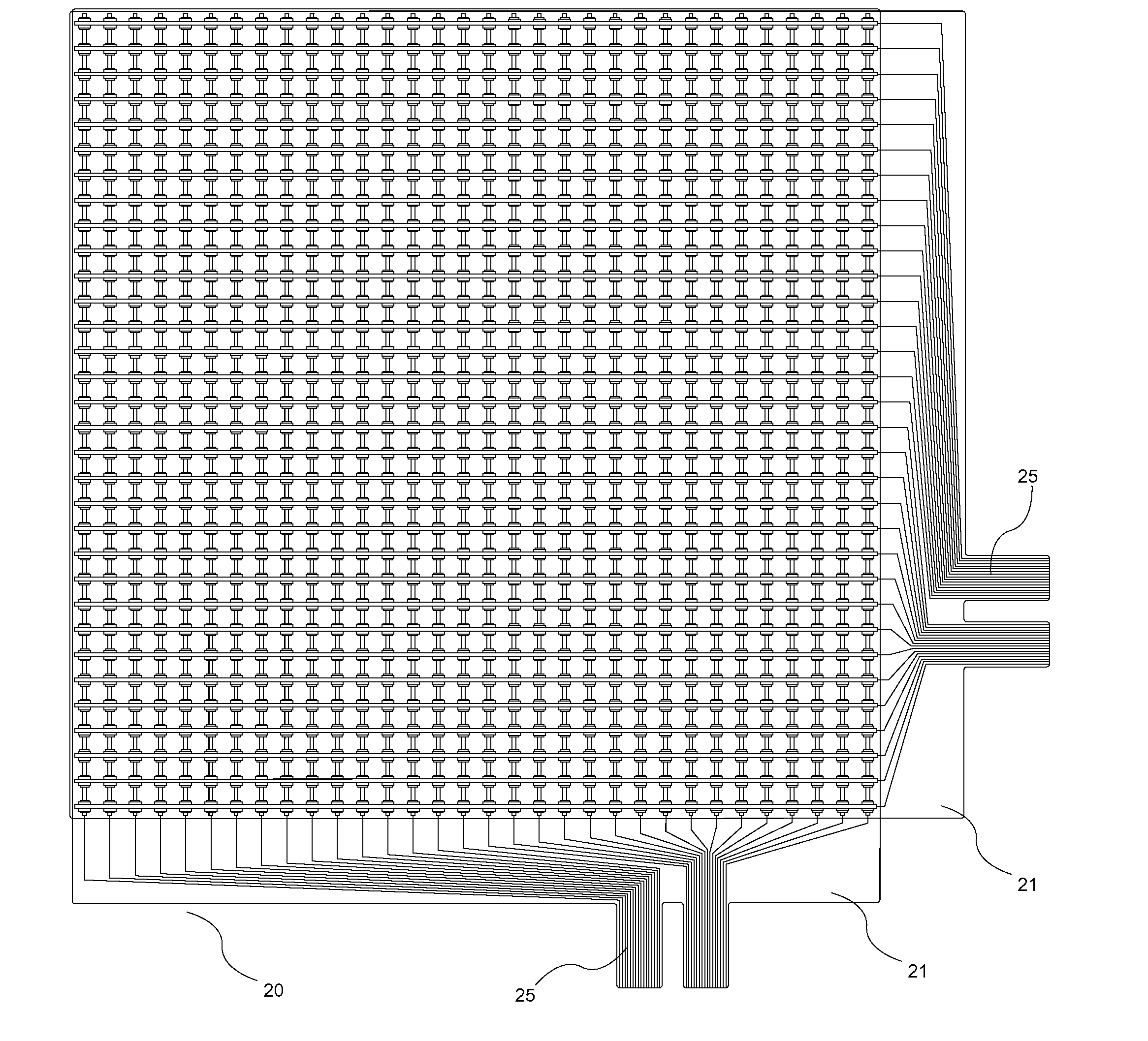
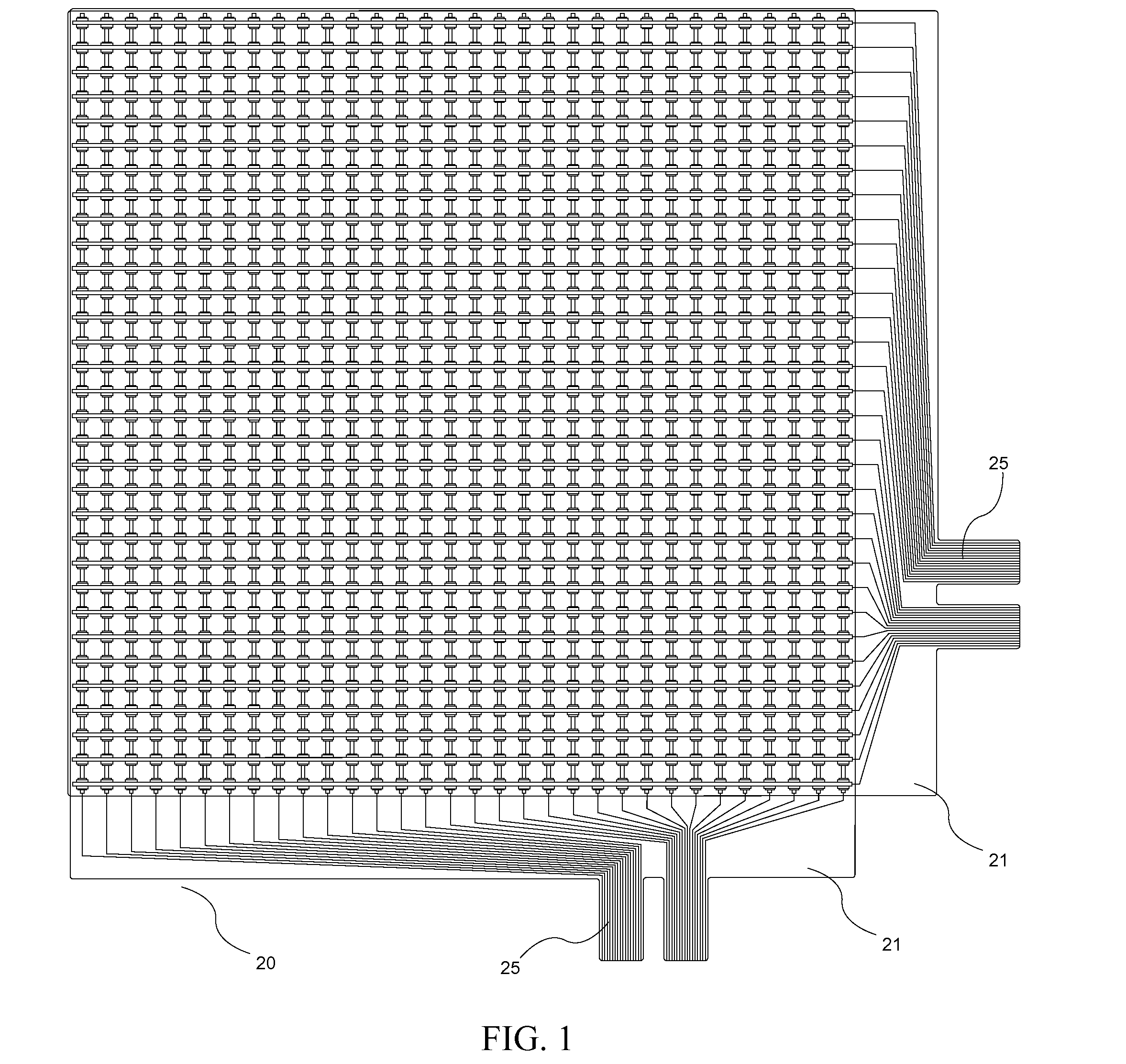
A sensor having a set of grid of bars that are in contact from their bottom at the corners with a set of protrusions that are in contact from above with a plurality of intersections, each having a sensing element, of a grid of wires disposed on a base, and a top surface layer that is disposed atop the grid of bars, so that force imparted from above onto the top surface layer is transmitted to the grid of bars and thence to the protrusions, and thence to the intersections of the grid of wires which are thereby compressed between the base and protrusions; and that the protrusions above thereby focus the imparted force directly onto the intersections. A sensor includes a computer in communication with the grid of wires which causes prompting signals to be sent to the grid of wires and reconstructs a continuous position of force on the surface from interpolation based on data signals received from the grid of wires. A method for sensing.
Description
CROSS-REFERENCE TO RELATED APPLICATIONS[0001]This application claims priority from U.S. provisional application Ser. No. 61 / 686,472 filed Apr. 5, 2012, and is a continuation-in-part of U.S. patent application Ser. No. 13 / 317,138 filed Oct. 11, 2011; which claims priority from U.S. provisional patent application 61 / 404,897 filed Oct. 12, 2010; and from U.S. provisional patent application 61 / 462,789 filed Feb. 8, 2011; and from U.S. provisional patent application 61 / 572,642 filed Jul. 19, 2011; and from U.S. provisional patent application 61 / 572,938 filed Jul. 25, 2011, all of which are incorporated by reference herein.FIELD OF THE INVENTION[0002]The present invention is related to a sensor which reconstructs a continuous position of force on a surface from interpolation based on data signals received from a grid of wires. (As used herein, references to the “present invention” or “invention” relate to exemplary embodiments and not necessarily to every embodiment encompassed by the app...
Claims
Login to View More Application Information
Patent Timeline
 IPC IPC(8): G06F3/00
CPCG06F3/005G06F3/045G06F2203/04103G06F2203/04112G06F2203/04113G06F3/04144G01L5/228G01L1/205G06F3/0414G06F3/044
InventorPERLIN, KENNETHHENDEE, CHARLESGRAU, ALEXSEIDMAN, GERALD
OwnerTACTONIC TECH