MEMS gyroscopes with reduced errors

a gyroscope and error reduction technology, applied in the field of gyroscope structure and circuitry, can solve the problems of limiting the useable capping pressure, limiting the noise that can be achieved as reasonable yield, and limiting the manufacture cost of such gyroscopes. the effect of driving coriolis

Active Publication Date: 2013-10-31
ANALOG DEVICES INC
View PDF0 Cites 39 Cited by
  • Summary
  • Abstract
  • Description
  • Claims
  • Application Information

AI Technical Summary

Benefits of technology

[0017]In one embodiment, a method of reducing drive-induced Coriolis accelerometer offset in a comb-drive vibratory gyroscope having a shuttle and a Coriolis accelerometer involves driving vibratory motion of the shuttle using a drive signal having alternating phase and anti-phase drive signal periods and demodulating output of the Coriolis accelerometer during equal times of phase and anti-phase drive of the shuttle with respect to the velocity signal used for angular rate demodulation.

Problems solved by technology

A major element in the cost of manufacture of such gyroscopes is measurement and correction of both sensitivity to angular rate and output in the absence of angular rate (null bias), especially as functions of temperature.
a) Variability of critical dimensions (CD) within a structure causes mismatch of shuttle frequencies and is the primary cause of Q variation and consequently rate sensitivity error. It also limits the useable capping pressure, which in turn limits the noise that can be achieved as reasonable yield.
b) Variability of fill gas pressure and composition during capping also causes variation in Q and variation of sensitivity with temperature. It interacts with (a) in a complex way.
c) Variability of CD within a structure causes mismatch of drive finger lateral forces, which is a major cause of null bias error.
d) In the presence of an effective quadrature servo, the main cause of null variability with packaging, user mounting and temperature is die stress which also mismatches lateral drive gaps.
Such calibration is time-consuming and complex, and requires specialized calibration equipment.
Thus, calibration is major cost contributor.
In addition to calibration and the costs associated with calibration, gyroscopes often include structural and electronic components that are used to mitigate null bias and angular rate sensitivity errors (e.g., trim electrodes and related circuitry), and these components can add cost and complexity to the gyroscope.
However, none of these devolve the absolute sensitivity from a plethora of electronics gains, and therefore calibration is still needed.
Thermal and mounting variation of null bias can be mitigated using a variety of methods for mechanically isolating the die (as for example, described by Harney et al., U.S. Pat. No. 6,768,196), but these involve additional fabrication and packaging expense.
However, the filters required are dependent on Q, which makes them difficult to implement in practice without adversely affecting dynamic errors or incurring some calibration technique.

Method used


Image

  • MEMS gyroscopes with reduced errors
  • MEMS gyroscopes with reduced errors
  • MEMS gyroscopes with reduced errors

Examples


exemplary embodiment 1

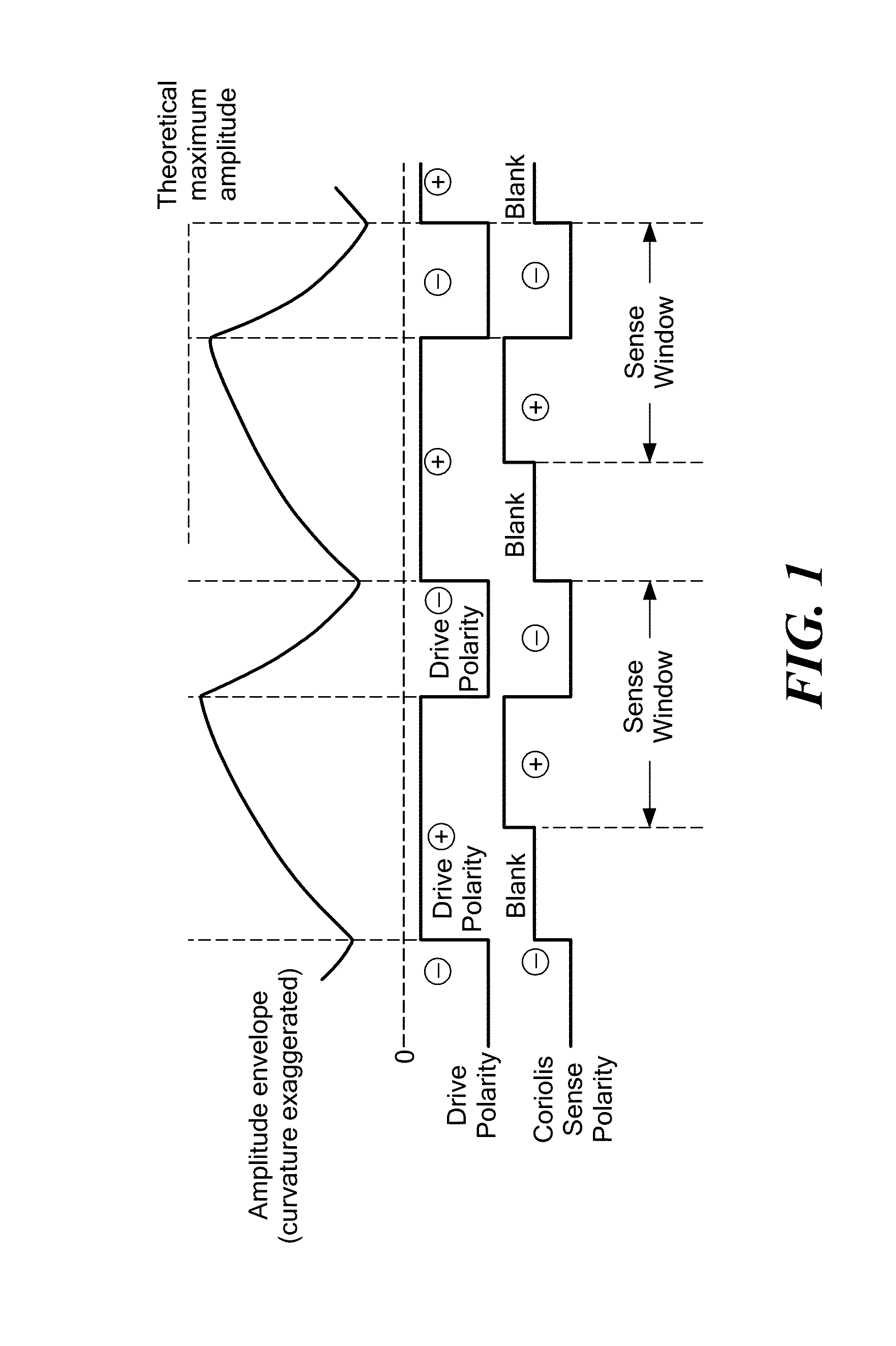
[0053]In one exemplary embodiment, during steady state operation (i.e., after initial startup of the shuttle resonance), the shuttle is driven using alternating phase (+) and anti-phase (−) drive signals such that the shuttle's amplitude (which is continually ramping up and down) increases during the phase period and decreases during the anti-phase period without reaching zero and also without reaching the theoretical maximum shuttle amplitude. Also, provided the Coriolis demodulation is co-phased with the shuttle velocity feedback, the error from drive gap mismatch is effectively reversed for half the time and effectively cancels out.

[0054]FIG. 1 schematically shows the amplitude envelope, drive polarity, sense polarity, and Coriolis sense window relationships for a first exemplary embodiment. In this exemplary embodiment, during steady state operation (i.e., after initial startup of the shuttle resonance), the shuttle is driven using alternating phase (+) and anti-phase (−) drive ...

exemplary embodiment 2

[0060]In another exemplary embodiment, the shuttle is alternately driven with a phase (+) signal for a fixed number of cycles to build the resonant motion through the essentially linear initial portion of its exponential growth and then driven with an anti-phase (−) signal for the same number of cycles to cancel that motion. In this exemplary embodiment, the amplitude of the shuttle motion periodically crosses zero. The use of equal numbers of phase and anti-phase cycles to continually ramp the amplitude of the shuttle oscillation effectively defines the shuttle Q. For example, if the drive is supplied for a duration N times the shuttle period, then the effective Q becomes πN / 2 averaged over that duration, provided the equilibrium Q is sufficiently greater than N. Since the output (sense) signal produced by the gyroscope is based on Q, this ability to define Q eliminates the need to measure Q. Thus, very low pressure, otherwise unusable because of frequency split, actually becomes a...


PUM


Abstract

In comb drive vibratory gyroscopes, drive-induced Coriolis accelerometer offset is effectively canceled by demodulating the output during equal times of in-phase and anti-phase drive of the shuttle with respect to the velocity signal used for angular rate demodulation. This reduces or eliminates the corresponding thermal and die-stress effects otherwise needing calibration.

Description

FIELD OF THE INVENTION[0001]The present invention relates generally to MEMS gyroscopes, and, more particularly, to MEMS gyroscope structure and circuitry to reduce null bias errors and increase sensitivity in order to reduce or eliminate the need for calibration for many gyroscope applications.BACKGROUND OF THE INVENTION[0002]Micromachined (MEMS) gyroscopes have become established as useful commercial items. Generally speaking, a MEMS gyroscope incorporates two high-performing MEMS devices, specifically a self-tuned resonator in the drive axis and a micro-acceleration sensor in the sensing axis. Gyroscope performance is very sensitive to such things as manufacturing variations, errors in packaging, driving, linear acceleration, and temperature, among other things. Basic principles of operation of angular-rate sensing gyroscopes are well understood and described in the prior art (e.g., Geen, J. et al., New iMEMS Angular-Rate-Sensing Gyroscope, Analog Devices, Inc., Analog Dialog 37-0...

Claims


Application Information

Patent Timeline
Patent Type & Authority Applications(United States)
IPC IPC(8): G01P3/44
CPCG01C19/5719G01C19/574G01C19/5755
Inventor GEEN, JOHN A.CHANG, JOHN F.
Owner ANALOG DEVICES INC
Why Eureka
Try Eureka