Device for forming a groove

a technology of a device and a groove, which is applied in the field of devices for forming grooves, can solve the problems of different types of behavior during the processing, heavy wear and tear, and need to replace them regularly, and achieve the effect of easy and careful scoring of even sensitive sheets

Inactive Publication Date: 2013-11-07
MULLER MARTINI HLDG
View PDF9 Cites 4 Cited by
  • Summary
  • Abstract
  • Description
  • Claims
  • Application Information

AI Technical Summary

Benefits of technology

[0007]It is an object of the present invention to create a device of the aforementioned type, which permits an easy and careful scoring of even sensitive sheets.
[0012]In one embodiment, the two knife edges can respectively be rounded off with a radius, which allows a careful compressing and / or displacement of the material.
[0016]In one embodiment, the scoring knife is positioned on a sensing wheel, which is pressed with an adjustable force against the score anvil, as shown in the European patent document EP 1 845 046 A1. The spacing between the two knife edges of the scoring knife and the score anvil is kept constant by the sensing wheel, regardless of the rotation of the score anvil, thus ensuring that the depth of a groove scored with the scoring knife in a sheet remains constant, regardless of the sheet thickness. If the scoring knife is furthermore connected with an eccentric connection to the sensing wheel, as shown in the European patent document EP 1 845 046 A1, the scoring depth can be adjusted very easily by turning this connection. An adjustment is necessary only during the changeover from very thin to very thick sheets or multi-page materials and vice versa.
[0017]In another embodiment, when folding a sheet along the deformation generated with the scoring knife, the fibers of a sheet are respectively bent by approximately 90° for each of the closely adjacent scoring grooves. With a scoring knife according to the prior art, having a single knife edge, the legs of the sheet that are bent by about 180° have a clearly higher tendency to tear or break. This unexpected and surprising effect achieved with the spaced-apart knife edges illustrates that the scoring device according to the invention is extremely tolerant and user-friendly with respect to adjusting the scoring depth and the contact pressure.
[0018]According to a further embodiment, the scoring knife can have a two-part design or a multipart design, meaning the axial distance between the side surfaces of the groove or between the knife edges can be adjusted, which allows the processing of an even broader product spectrum.

Problems solved by technology

The aforementioned embossing device is suitable for use with thicker products, but not with thin products such as covers for magazines or other types of printed products.
If the strips are made of plastic, as described, they are subject to heavy wear and tear and must be replaced regularly with new ones.
To obtain an optimum groove or perforation in the flat materials to be processed, the strips must be attached to the drum circumference with extreme precision in an axial, as well as radial, direction, an operation that can be very time-consuming and involved.
Differences in the quality and types of materials, such as non-printed or printed sheets, signatures, or foils also result in different types of behavior during the processing.
Thus, it is known that sensitive sheets have a tendency to tear or break when they are folded along deformations caused by scoring, in particular if individual printed sheets are used as casings for books, softcovers or the like.
If the contact pressure is too low, the fold may deviate from the intended bending location after the scoring.

Method used


Image

  • Device for forming a groove
  • Device for forming a groove
  • Device for forming a groove

Examples


Embodiment Construction

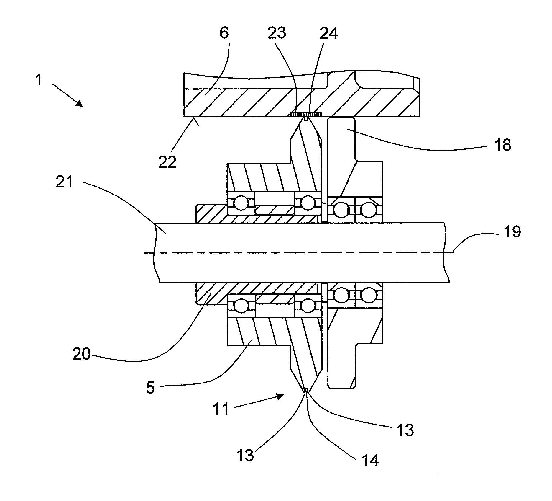
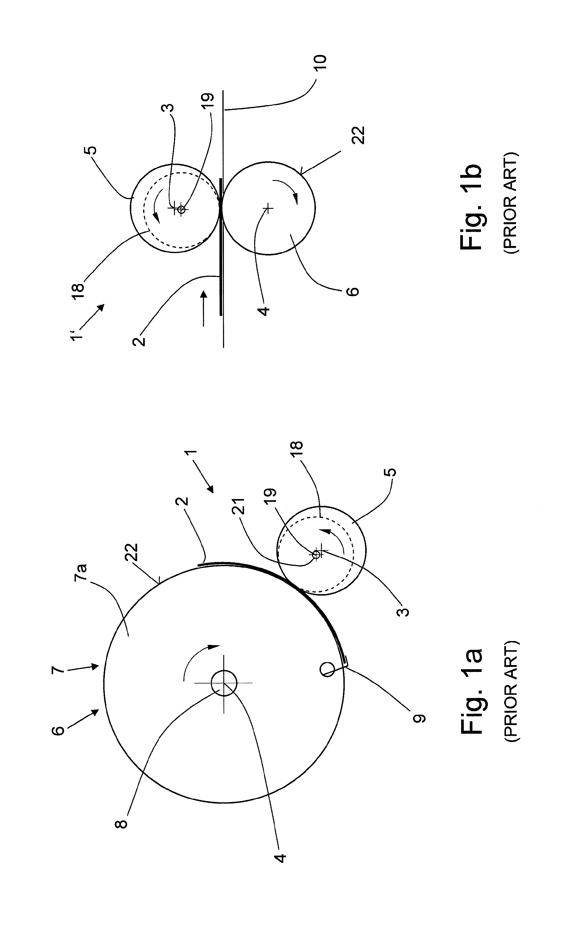
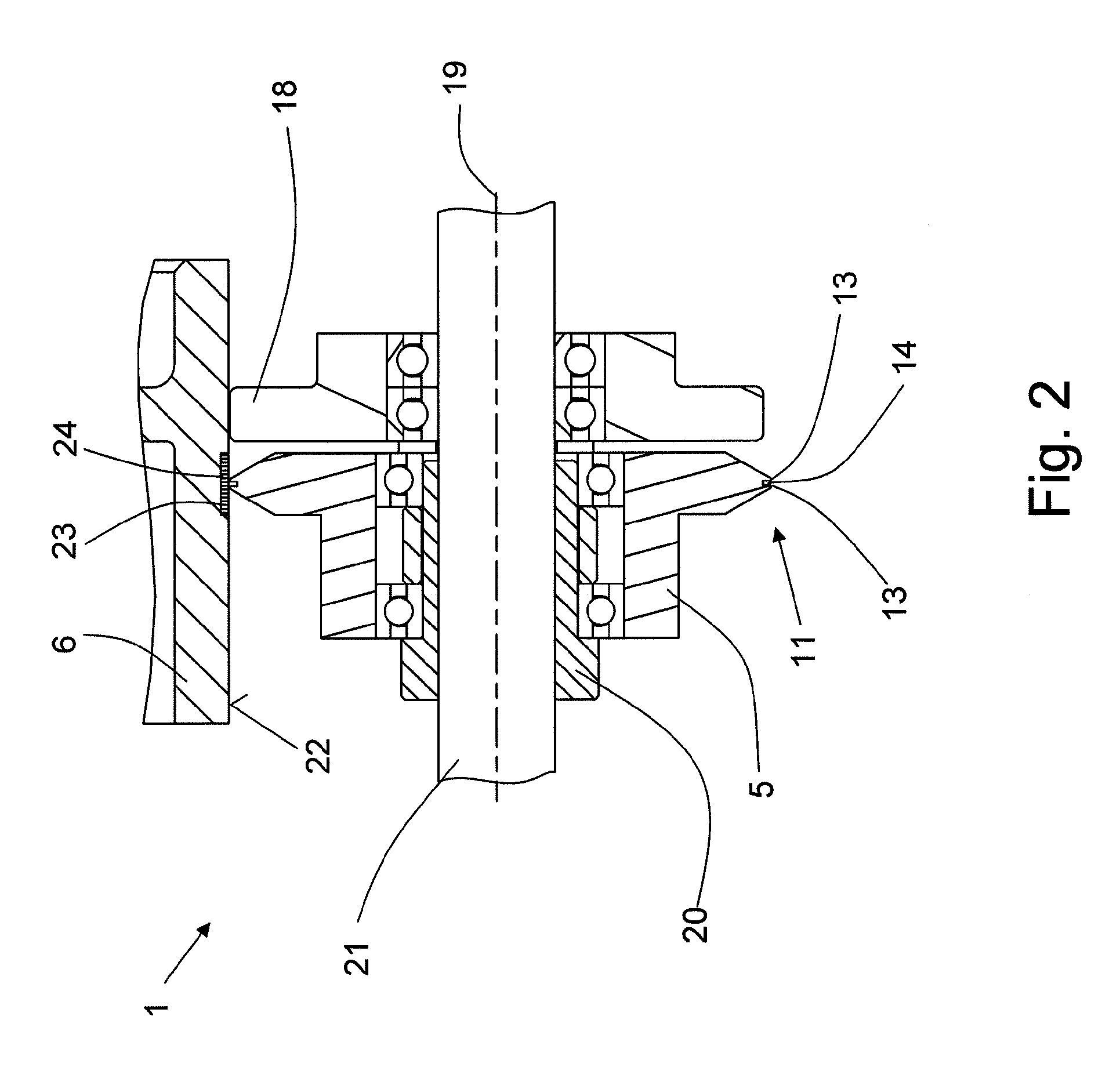
[0036]FIGS. 1a and 1b schematically show a device 1 and 1′, respectively, for the scoring of material in the form of a single-page or multi-page sheets or a web of paper, plastic or metal. In the following, these different products and materials, either imprinted or not imprinted, are referred to as a cover 2. The device 1, 1′ consists of at least two scoring elements that rotate around parallel axes 3, 4. A first scoring element is embodied as a scoring knife 5 while a second scoring element is embodied as a score anvil 6. FIG. 1a shows a cover 2, which is pulled from a stack that is not shown herein and is conveyed in clockwise direction with the aid of a drum 7 connected to the shaft 8. The drum 7 consists of at least two spaced-apart drum discs (only one drum disc 7a being shown), provided along the periphery with respectively at least one gripper 9 for holding the covers 2. The score anvil 6 can be a component of a drum disc or can be mounted between these drum discs on the sha...


PUM

PropertyMeasurementUnit
depthaaaaaaaaaa
angleaaaaaaaaaa
angleaaaaaaaaaa

Abstract

A device for forming a groove in a cover, the device including a circular score anvil having a first axis and being rotatable in a first direction and a circular scoring knife having a second axis positioned parallel to the first axis and arranged radially opposite the circular score anvil to define a gap between the score anvil and the scoring knife. The scoring knife is rotatable in a second direction opposite to the first direction and comprises a scoring element having an edge region that is tapered to form a ridge toward a periphery of the element. The edge region includes an intermediate space that divides the edge region into two spaced apart knife edges. A groove is formed in the cover while moving through the gap by operative cooperation of the scoring knife and score anvil.

Description

CROSS-REFERENCE TO RELATED APPLICATION[0001]This application is a Continuation of U.S. patent application Ser. No. 12 / 470,847, filed May 22, 2009, which claims the priority of European Patent Application No. EP 08157121.8, filed on May 28, 2008, all of which are incorporated herein by reference.BACKGROUND OF THE INVENTION[0002]The invention relates to a device for forming a groove on a single-page or multi-page sheet or on a web of paper, plastic or metal, passing through an annular gap between two circular scoring elements that rotate in opposite directions around parallel axes, wherein one scoring element is embodied as a scoring knife that is tapered toward the edge region in the manner of a ridge and the opposite-arranged scoring element is embodied as a score anvil.[0003]Devices of this type are disclosed, for example, in the European patent document EP 0 627 303 A1, WIPO patent document WO 2004 / 073966 A1 and European patent document EP 1 845 046 A1.[0004]The European patent do...

Claims


Application Information

Patent Timeline
Patent Type & Authority Applications(United States)
IPC IPC(8): B26D3/06B31B50/25
CPCB26D3/06B31F1/10B31B50/254B31B50/256Y10T83/037Y10T83/148Y10T83/0215Y10T83/0304Y10T83/0341
Inventor WALIAN, HARALD
Owner MULLER MARTINI HLDG
Why Eureka
Try Eureka