

Device for forming a groove
- Summary
- Abstract
- Description
- Claims
- Application Information
AI Technical Summary
Benefits of technology
Problems solved by technology
Method used
Image

Examples
Embodiment Construction
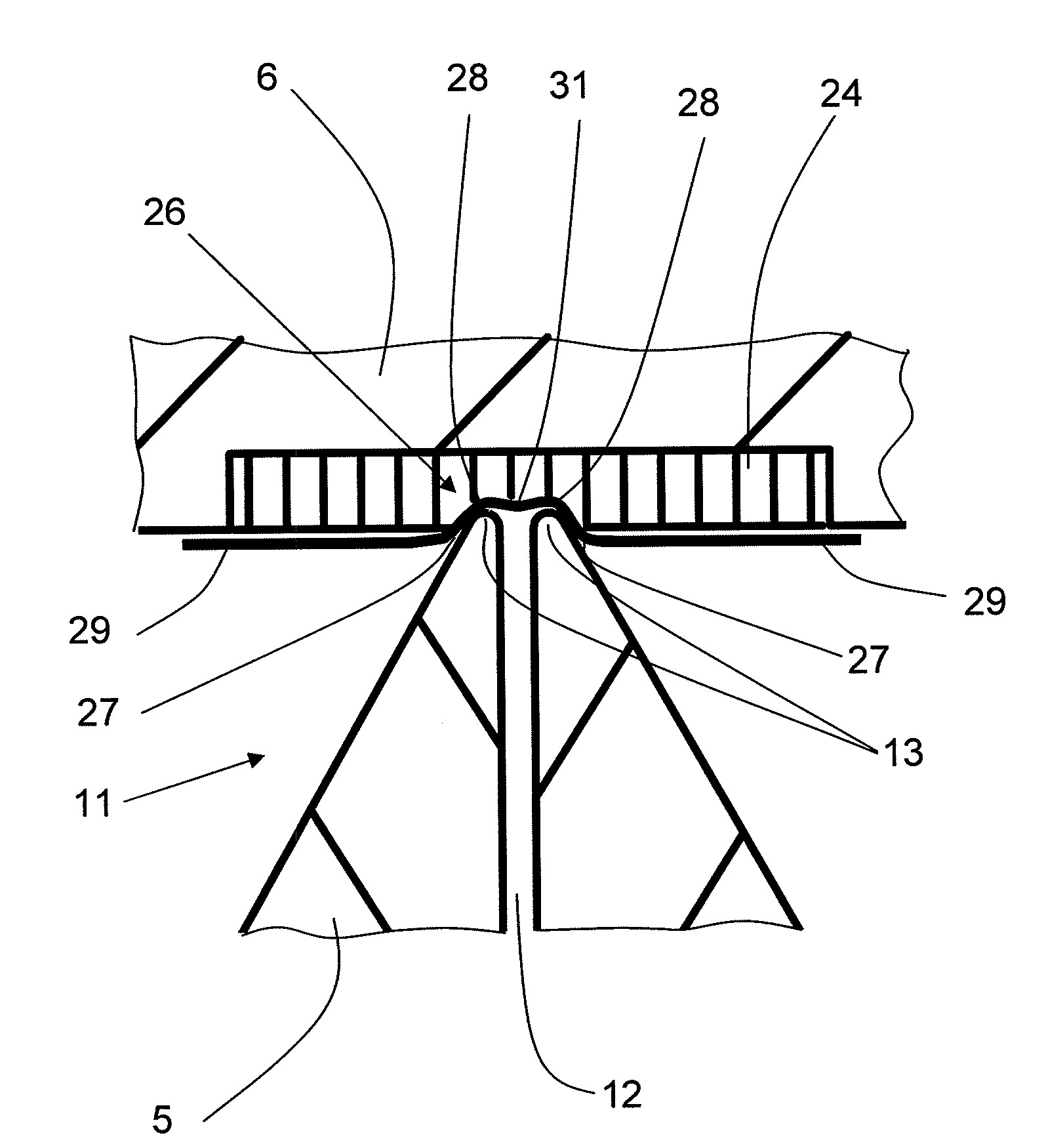
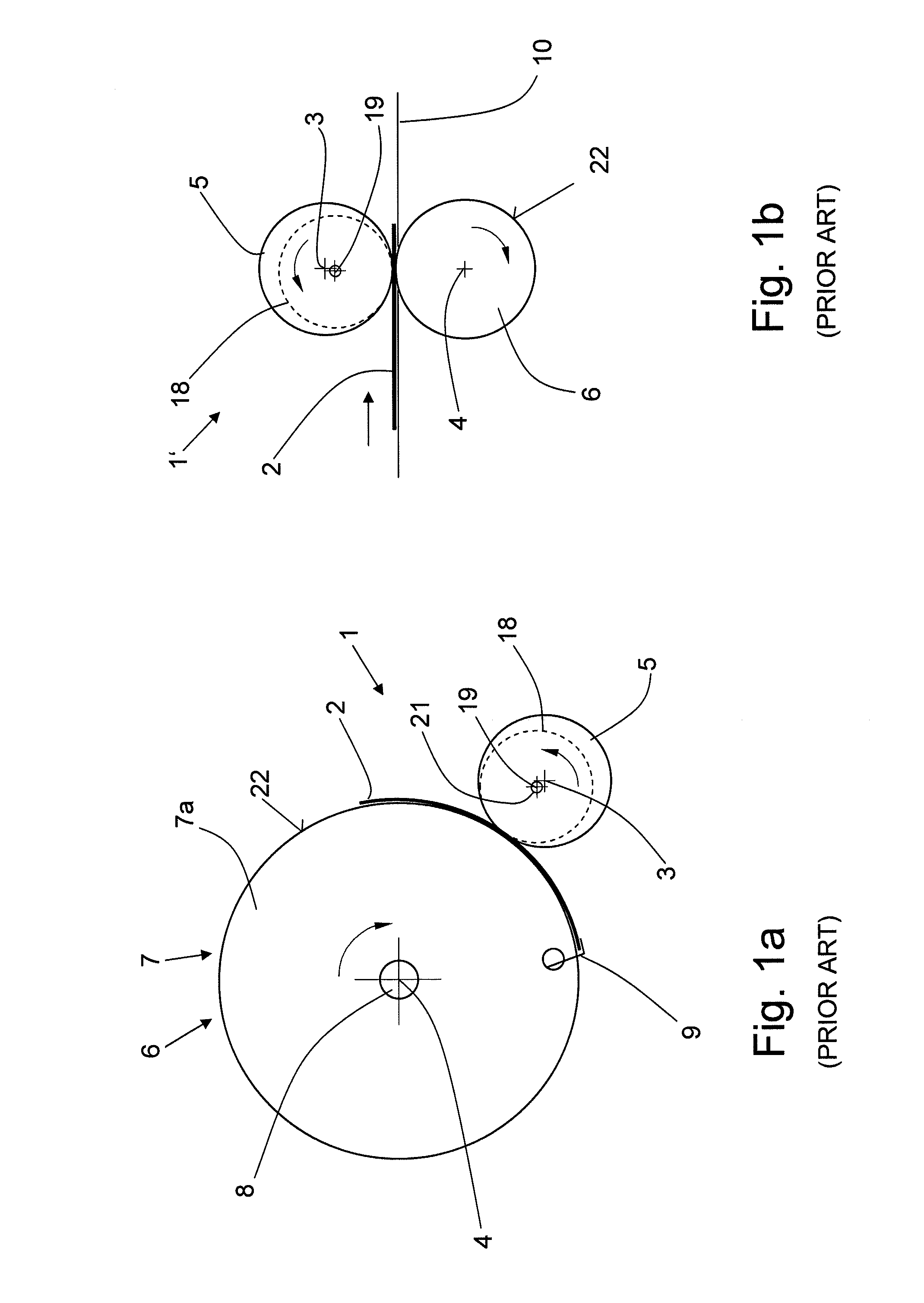
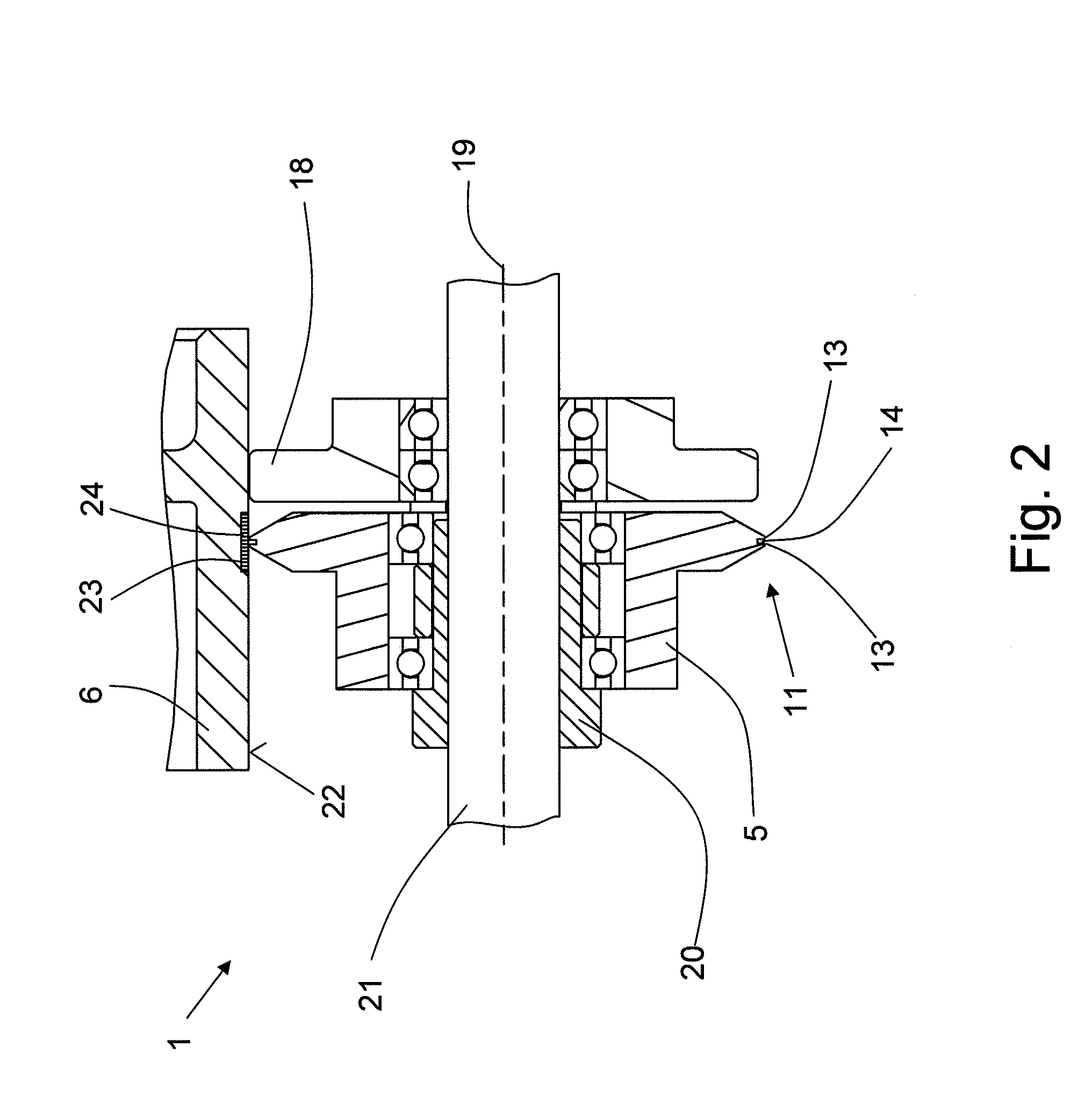
[0036]FIGS. 1a and 1b schematically show a device 1 and 1′, respectively, for the scoring of material in the form of a single-page or multi-page sheets or a web of paper, plastic or metal. In the following, these different products and materials, either imprinted or not imprinted, are referred to as a cover 2. The device 1, 1′ consists of at least two scoring elements that rotate around parallel axes 3, 4. A first scoring element is embodied as a scoring knife 5 while a second scoring element is embodied as a score anvil 6. FIG. 1a shows a cover 2, which is pulled from a stack that is not shown herein and is conveyed in clockwise direction with the aid of a drum 7 connected to the shaft 8. The drum 7 consists of at least two spaced-apart drum discs (only one drum disc 7a being shown), provided along the periphery with respectively at least one gripper 9 for holding the covers 2. The score anvil 6 can be a component of a drum disc or can be mounted between these drum discs on the sha...
PUM
| Property | Measurement | Unit |
|---|---|---|
| Angle | aaaaa | aaaaa |
| Flexibility | aaaaa | aaaaa |
| Width | aaaaa | aaaaa |
Abstract
Description
Claims
Application Information