
Osteosynthesis plate for lumbosacral joint

a technology for lumbosacral joints and plates, applied in the field of plates for lumbosacral joint osteosynthesis, can solve the problems of difficult implementation, difficult to achieve, and difficult to access the intervertebral disk, and achieve the effect of reducing or no mobilization

Active Publication Date: 2013-11-07
MEDICREA INT SA
View PDF14 Cites 3 Cited by
  • Summary
  • Abstract
  • Description
  • Claims
  • Application Information

AI Technical Summary

Benefits of technology

The patent describes an implant for spinal surgery that can securely stabilize the spine. The implant has two holes with different directions for screw placement, which ensures perfect anchoring to the spine and helps prevent mobility. The implant also has sharp projections that allow for easy prepositioning and complementary immobilization of the spine relative to the sacrum. Overall, the implant improves the stability and integrity of spinal surgery procedures.

Problems solved by technology

This approach does, however, have the drawbacks of not allowing very easy access to the intervertebral disk and of being delicate to implement given the proximity to the spinal cord.
It does, however, have the significant drawback of not guaranteeing complete immobilization of the fifth lumbar vertebra, which is not without impact on the osteosynthesis performed.
This plate allows better fastening in the fifth lumbar vertebra, but has the significant drawback of requiring a substantial and delicate immobilization of the bifurcations of the vena cave and the aorta, making the operation much more complex.

Method used


Image

  • Osteosynthesis plate for lumbosacral joint
  • Osteosynthesis plate for lumbosacral joint
  • Osteosynthesis plate for lumbosacral joint

Examples


Embodiment Construction

[0044]For simplification, the elements that appear identically or similarly from one embodiment to the next will be designated using the same numerical references and will not be described again.

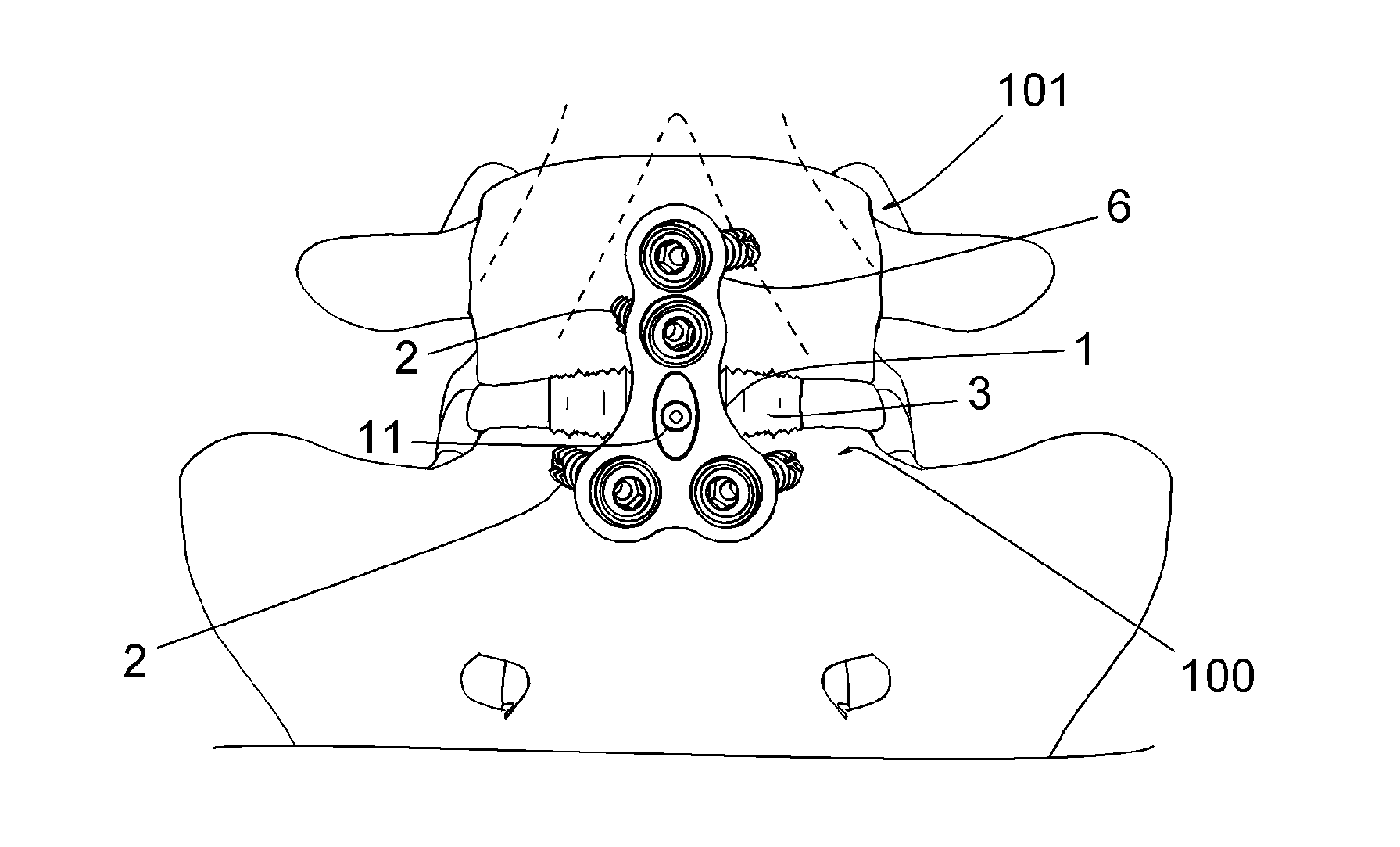
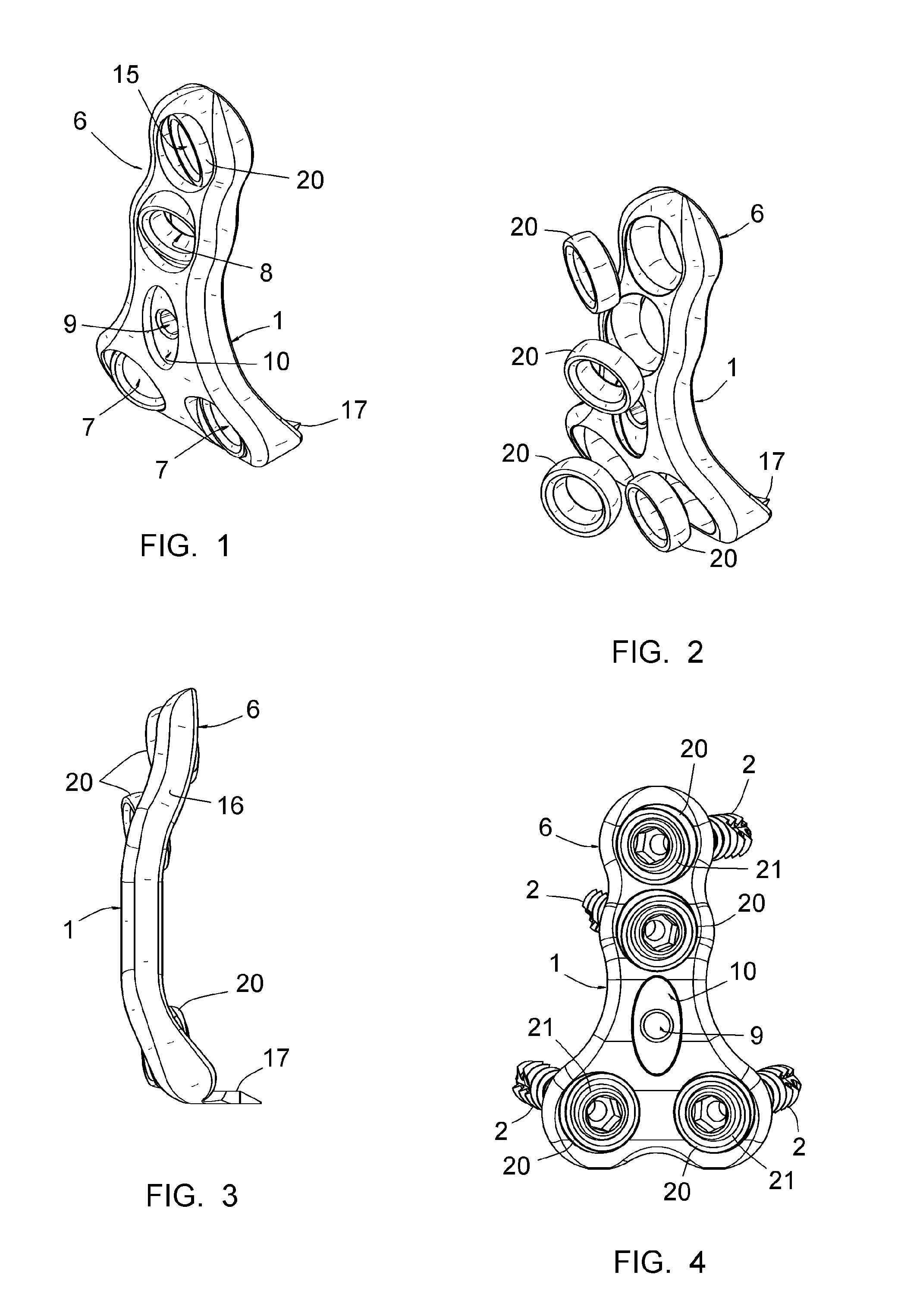
[0045]FIGS. 1 to 4 show a plate 1 for the osteosynthesis of the lumbosacral joint. As appears in FIGS. 7 to 9, this plate 1 is intended to be placed on the first vertebra 100 of the sacrum and the fifth lumbar vertebra 101 and to be fixed to said vertebrae using screws 2. It can in particular be connected to an intervertebral implant 3 inserted between the plates of said vertebrae 100, 101, as shown by FIG. 7.

[0046]In reference to FIGS. 1 to 4, the plate 1 assumes a generally triangular shape, with rounded corners and concave edges, and comprises an upper extension 6. It will be understood that the terms “lower” and “upper” must be considered in relation to what is located in the lower position or upper position of the plate after implantation on a patient.

[0047]The plate 1 is intended to co...


PUM


Abstract

The plate (1) has a generally triangular shape and includes two juxtaposed lower holes (7), intended to receive implantation screw (2) in the sacrum (100), and a first upper hole (8) for receiving an implantation screw (2) in the fifth lumbar vertebra (101). According to the invention, the plate (1) includes an extension (6) integral therewith, extending its upper side, i.e. protruding from the side opposite the two juxtaposed lower holes (7), the extension (6) having a second upper hole (15) formed in its entirety thereon, for receiving a second screw (2) intended to be implanted in the fifth lumbar vertebra (101), and having, at all points of its length, a width not greater than two times the diameter of the second upper hole (15); the direction in which the extension (6) protrudes from the plate (1) is such that the first upper hole (8) and the second upper hole (15) are placed on a first line (L1) substantially perpendicular to a second line (L2) passing through the two juxtaposed lower holes (7).

Description

CROSS REFERENCE TO RELATED APPLICATION[0001]This application is a national stage entry of PCT / IB2012 / 050464 filed Feb. 1, 2012, under the International Convention claiming priority over French Application No. 1150885 filed Feb. 3, 2011.FIELD OF THE INVENTION[0002]The present invention relates to a plate for the osteosynthesis of the lumbosacral joint.BACKGROUND OF THE INVENTION[0003]It is well known to perform the osteosynthesis of two vertebrae in case of an ailment of the intervertebral disk, i.e. to perform an immobilization of those two vertebrae and a bone fusion thereof via the implantation of osteosynthesis material.[0004]A first technique consists of operating through the posterior route, and implanting, on the posterior side of the vertebrae, equipment with pedicular screws and connecting rods. This approach does, however, have the drawbacks of not allowing very easy access to the intervertebral disk and of being delicate to implement given the proximity to the spinal cord....

Claims


Application Information

Patent Timeline
IPC IPC(8): A61B17/70
CPCA61B17/7055A61B17/8047A61B17/7059
Inventor BIRCH, NICHOLAS
Owner MEDICREA INT SA
Learn More