
Resistive Devices and Methods of Operation Thereof

a technology of resistive devices and resistive devices, applied in the field of resistive devices, can solve the problems of flash memory having a number of limitations and a significant threat to the continued advancement of memory technology

Active Publication Date: 2013-11-14
GLOBALFOUNDRIES US INC
View PDF5 Cites 42 Cited by
  • Summary
  • Abstract
  • Description
  • Claims
  • Application Information

AI Technical Summary

Benefits of technology

The present invention solves or avoids certain problems and provides technical advancements. The technical effects of the invention provide solutions that address challenges and provide improved performance.

Problems solved by technology

However, Flash memory has a number of limitations that is posing a significant threat to continued advancement of memory technology.

Method used


Image

  • Resistive Devices and Methods of Operation Thereof
  • Resistive Devices and Methods of Operation Thereof
  • Resistive Devices and Methods of Operation Thereof

Examples


Embodiment Construction

[0023]The making and using of various embodiments are discussed in detail below. It should be appreciated, however, that the present invention provides many applicable inventive concepts that can be embodied in a wide variety of specific contexts. The specific embodiments discussed are merely illustrative of specific ways to make and use the invention, and do not limit the scope of the invention.

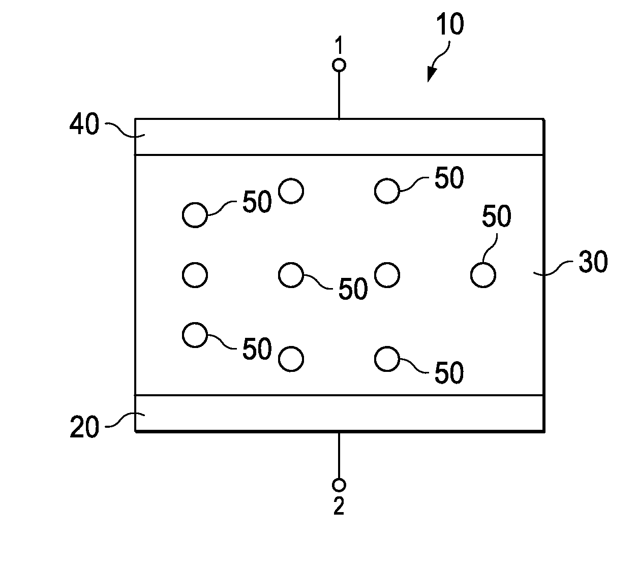
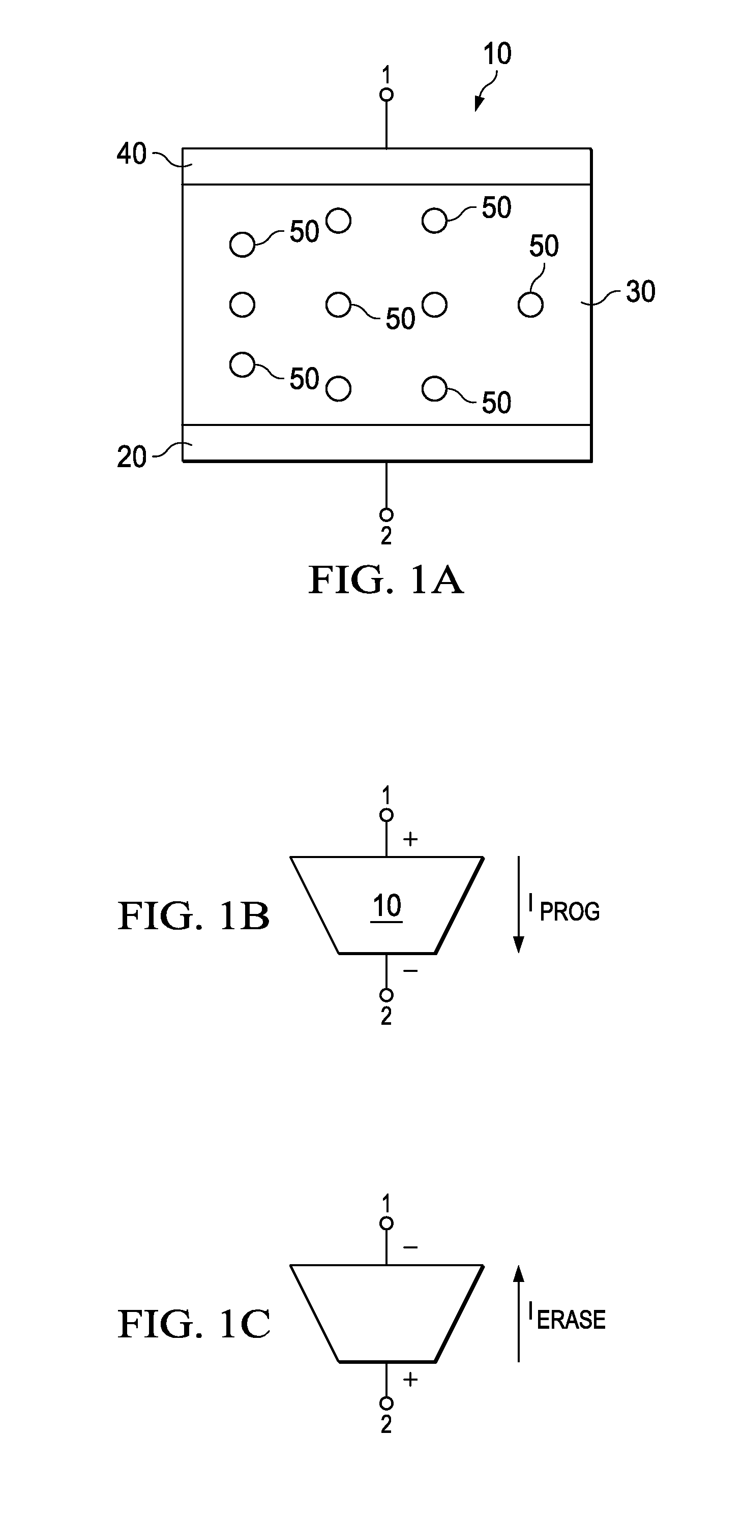
[0024]The present invention will be described with respect to various embodiments in a specific context, namely ionic memories such as conductive bridging memories. The invention may also be applied, however, to other types of memories, particularly, to any resistive memory such as two terminal resistive memories. Although described herein for a memory device, the embodiments of the invention may also be applied to other types of devices formed by resistive switching such as processors, dynamically-reroutable electronics, optical switches, field-programmable gate arrays, and microfluidic val...


PUM


Abstract

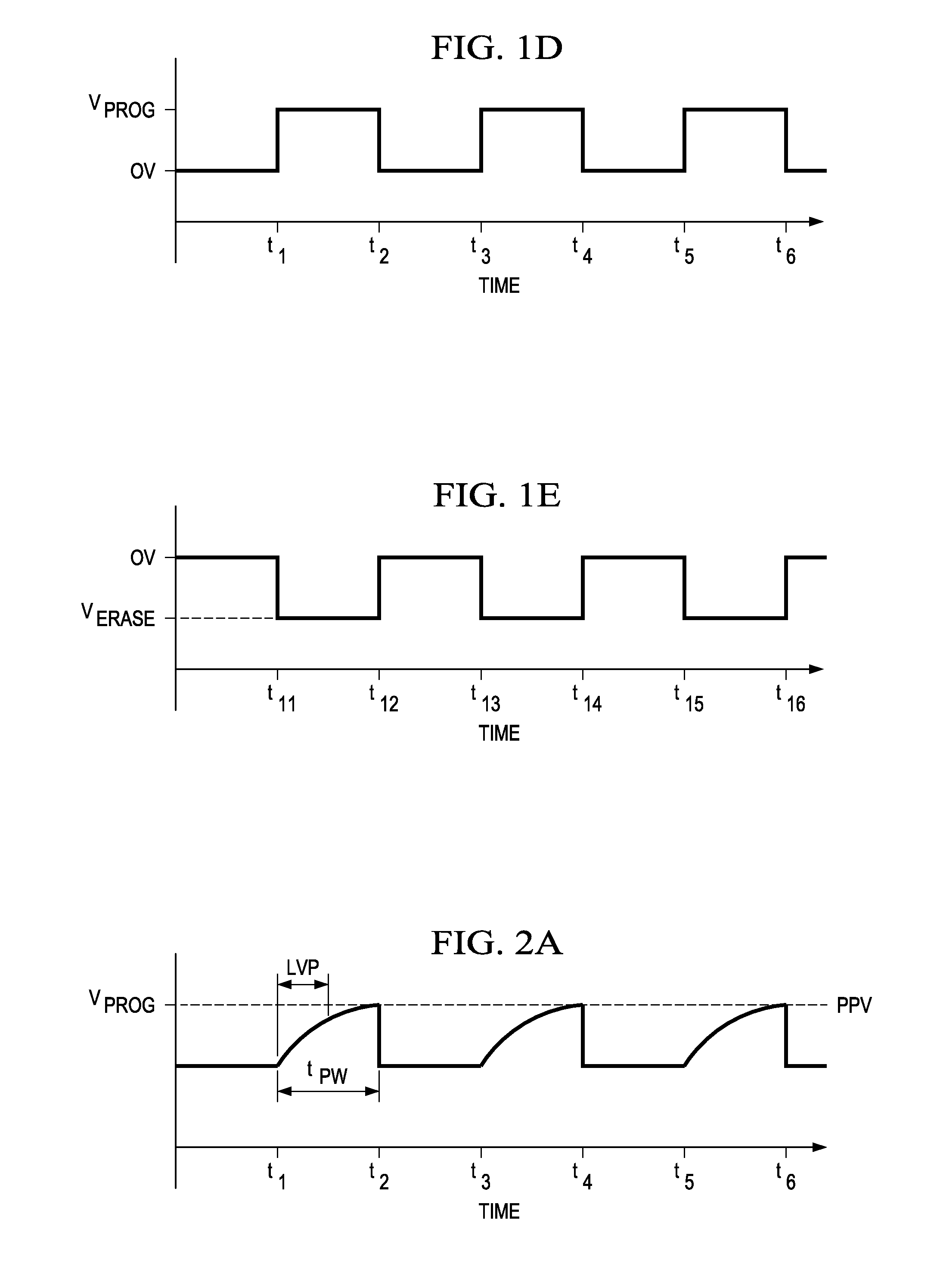
In one embodiment, a method of operating a resistive switching device includes applying a signal comprising a pulse on a first terminal of a two terminal resistive switching device having the first terminal and a second terminal. The resistive switching device has a first state and a second state. The pulse includes a first ramp from a first voltage to a second voltage over a first time period. The first time period is at least 0.1 times a total time period of the pulse.

Description

TECHNICAL FIELD[0001]The present invention relates generally to semiconductor devices, and in particular to resistive devices and methods of operation thereof.BACKGROUND[0002]Semiconductor industry relies on device scaling to deliver improved performance at lower costs. Flash memory is the mainstream non-volatile memory in today's market. However, Flash memory has a number of limitations that is posing a significant threat to continued advancement of memory technology. Therefore, the industry is exploring alternative memories to replace Flash memory. Contenders for future memory technology include magnetic storage random access memory (MRAM), ferroelectric RAM (FeRAM), and resistive switching memories such as phase change RAM (PCRAM), resistive RAM (RRAM), ionic memories including programmable metallization cell (PMC) or conductive bridging random access memory (CBRAM). These memories are also called as emerging memories.[0003]To be viable, the emerging memory has to be better than ...

Claims


Application Information

Patent Timeline
Patent Type & Authority Applications(United States)
IPC IPC(8): G11C11/00
CPCG11C13/003G11C13/0002G11C13/0004G11C13/0007G11C13/0011G11C13/0028G11C13/004G11C13/0061G11C13/0069G11C13/0097G11C2013/0071G11C2013/0092G11C2213/79
Inventor KAMALANATHAN, DEEPAKKOUSHAN, FOROOZAN SARAHECHEVERRY, JUAN PABLO SAENZDINH, JOHNHOLLMER, SHANE C.KOZICKI, MICHAEL
Owner GLOBALFOUNDRIES US INC
Learn More