Device for maintaining a tied shoe lace knot

Inactive Publication Date: 2013-12-05
BECKER MICHAEL A
View PDF19 Cites 4 Cited by
  • Summary
  • Abstract
  • Description
  • Claims
  • Application Information

AI Technical Summary

Problems solved by technology

This device was satisfactory, however it suffered from the disadvantage that it

Method used


Image

  • Device for maintaining a tied shoe lace knot
  • Device for maintaining a tied shoe lace knot
  • Device for maintaining a tied shoe lace knot

Examples


Embodiment Construction

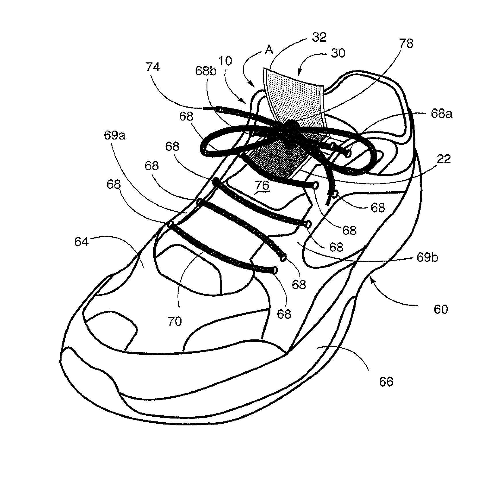
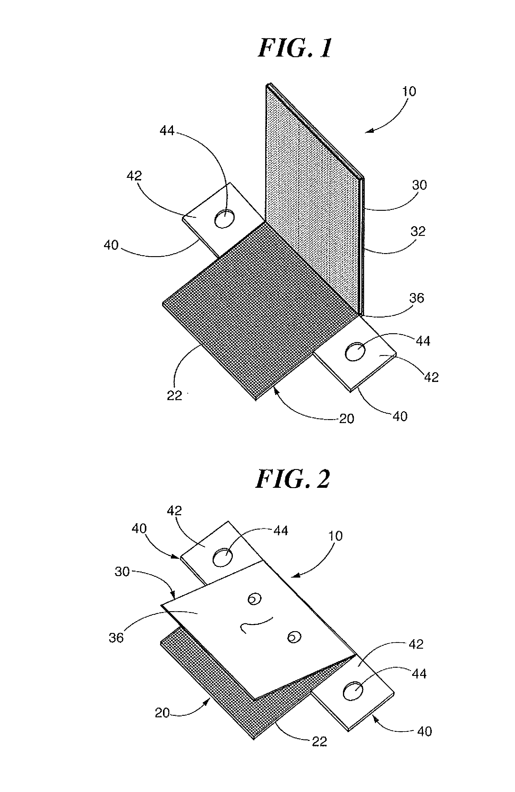
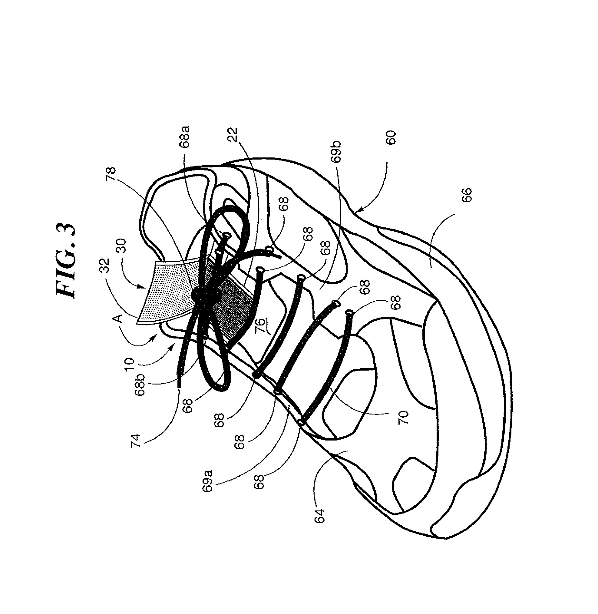
[0011]Reference is first made to FIGS. 1 and 2 wherein a device for securing a shoe lace, generally indicated as 10, is provided. Device 10 includes a first panel 20 having an interior surface 22. In a preferred embodiment, first panel 20 is sufficiently pliable so as to bend or give with the bending of the shoe upon which it is secured to prevent discomfort or dislodging of the shoe lace, during activities such as running, sports, or other play. in a preferred embodiment, the panels are made from twill, poplin, or a thin plastic sheet having the properties described herein.

[0012]Shoe lace securing members 40, extend from each of opposed sides of panel 20 and are substantially coaxial with each other relative to panel 20. Each shoe lace securing member includes a substrate 42 and a hole 44 formed therein. Hole 44 is sized and dimensioned to be capable of receiving a shoe lace therethrough; preferably in a tension fit. In this way shoe lace securing members 40 anchor panel 20 to the ...


PUM


Abstract

A device for securing a shoe lace has a first panel and a second panel affixed to the first panel. The second panel being movable about a fold line between a first position away from the first panel and a second position in contact with the first panel. A first shoe lace securing member extending from a first side of the first panel and a second shoe lace securing member extending from an opposed side of the first panel, each shoe lace securing member securing the first panel to a shoe. A fastener secures the first panel to the second panel when in contact with each other.

Description

CROSS REFERENCE TO RELATED APPLICATION[0001]This application claims priority to Provisional Patent Application No. 61 / 652,365, filed May 29, 2012, and is incorporated herein as set forth in its entiretyBACKGROUND OF THE INVENTION[0002]This application is related to an apparatus for securing shoe laces and, in particular, to a specific form of such an apparatus capable of maintaining a shoe lace in the tied position.[0003]Any parent knows that the shoe laces of their children elementary age and younger continuously seem to come untied. Therefore, the prior art recognizes the need to secure a shoe lace to the shoe. One such prior art device is known from U.S. Pat. No. 5,402,589 which has first and second jaws adapted to releasably capture at least a finished shoe lace knot. At least one jaw member is displaceable from the other jaw member as a jaw opening. The jaw also includes spacers secured to the tongue of the shoe providing a space between the entrance to the jaws and the shoe to...

Claims


Application Information

Patent Timeline
IPC IPC(8): A43C7/02
CPCA43C7/02A43C7/005Y10T24/3708
Inventor BECKER, MICHAEL A.
Owner BECKER MICHAEL A
Why Eureka
Try Eureka