Systems and methods for monitoring and displaying a patient's status

a system and status technology, applied in the field of monitoring and displaying the status of patients, can solve the problems of slowing down or degrading the clinical usefulness of acquired data, users usually, and limited ability to interface or manipulate the displayed data, so as to achieve accurate and easy display of the status of the patien

Inactive Publication Date: 2013-12-05
EDWARDS LIFESCIENCES CORP
View PDF11 Cites 54 Cited by
  • Summary
  • Abstract
  • Description
  • Claims
  • Application Information

AI Technical Summary

Benefits of technology

[0011]The disclosure relates to an interactive system for more accurately and easily displaying and monitoring a patient's status. In one embodiment, changes in a patient's hemodynamic status, including, but not limited to cardiac output, stroke volume, stroke volume variation, systemic vascular resistance, oxygen saturation, global end diastolic volume, global ejection fraction, and extravascular lung water. The system allows a user, such as a clinician or healthcare professional, to enter or trigger an event, intervention, therapy, or other notable change in a patient's status via a touch-enabled display screen. Upon triggering an event, the system records a patient's status as identified by graphical representations of various patient hemodynamic parameters, combined with a tabular or numerical representation of the patient hemodynamic status, or as a tabular numerical representation alone. The display of hemodynamic parameters may include the absolute value of the parameters, the percentage change in the parameters since an event was recorded, and an absolute percentage change within a previous time segment. The system and method provides a clinician with a direct view of the effects of a clinical event, and allows the clinician to determine a change in a patient's status as a result of the clinical event.

Problems solved by technology

Unfortunately, in order to present a large quantity of physiological data in a single screen in a meaningful manner, data presentation may be presented in less than intuitive fashion (e.g., replacing amplitude geometry with color indexing) and for some aspect of the data deemed to be “unimportant,” such data may be omitted or otherwise modified.
Some users of the equipment find such display representation to be visually unappealing and may result in slowing down or degrading the clinical usefulness of the acquired data.
Moreover, once display of the data has been initiated, users usually have limited ability to interface or manipulate the displayed data to further facilitate the clinical usefulness of the data for that particular user.
In addition, current systems allow only limited recording and displaying of patient parameters.

Method used


Image

  • Systems and methods for monitoring and displaying a patient's status
  • Systems and methods for monitoring and displaying a patient's status
  • Systems and methods for monitoring and displaying a patient's status

Examples


Embodiment Construction

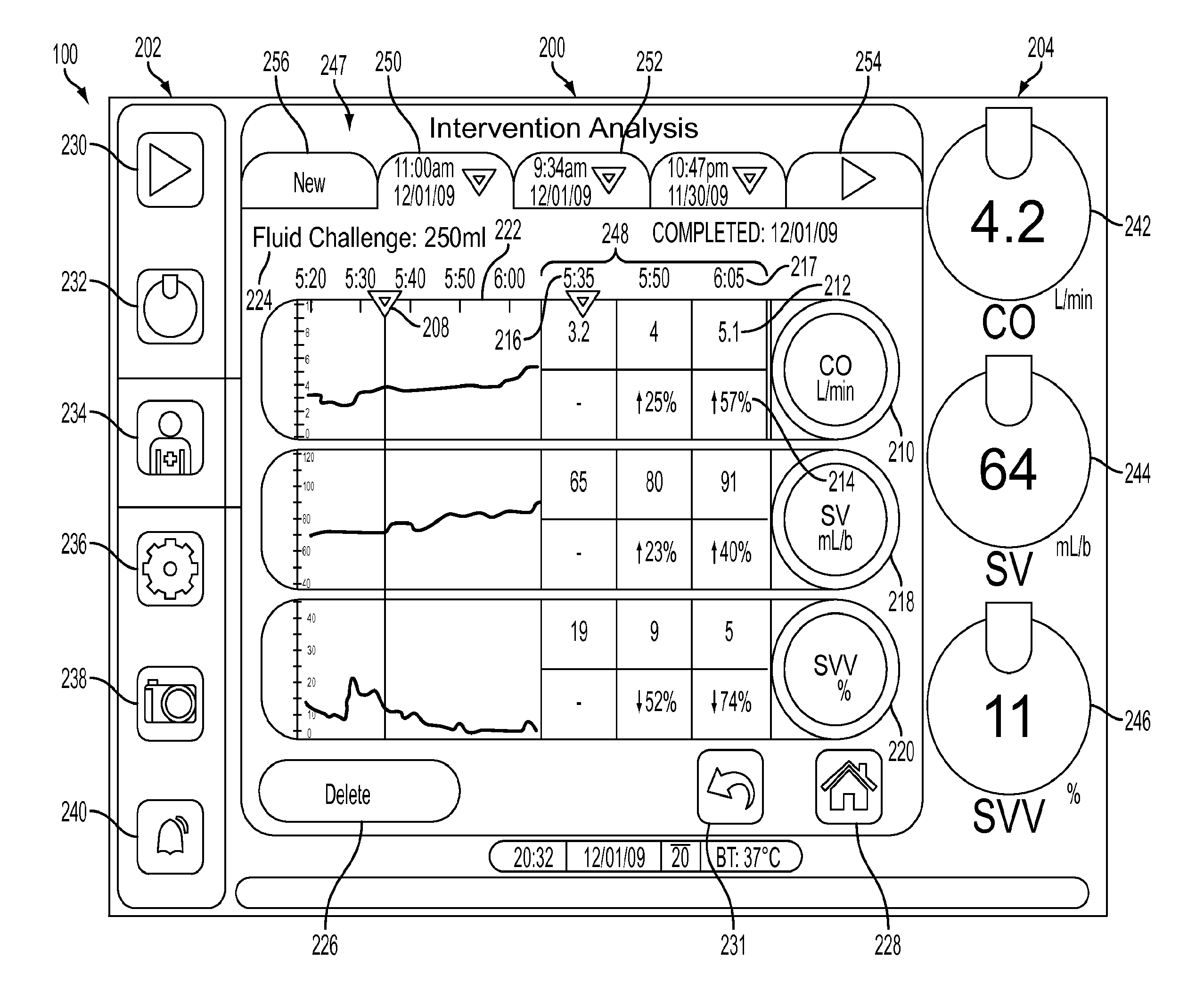
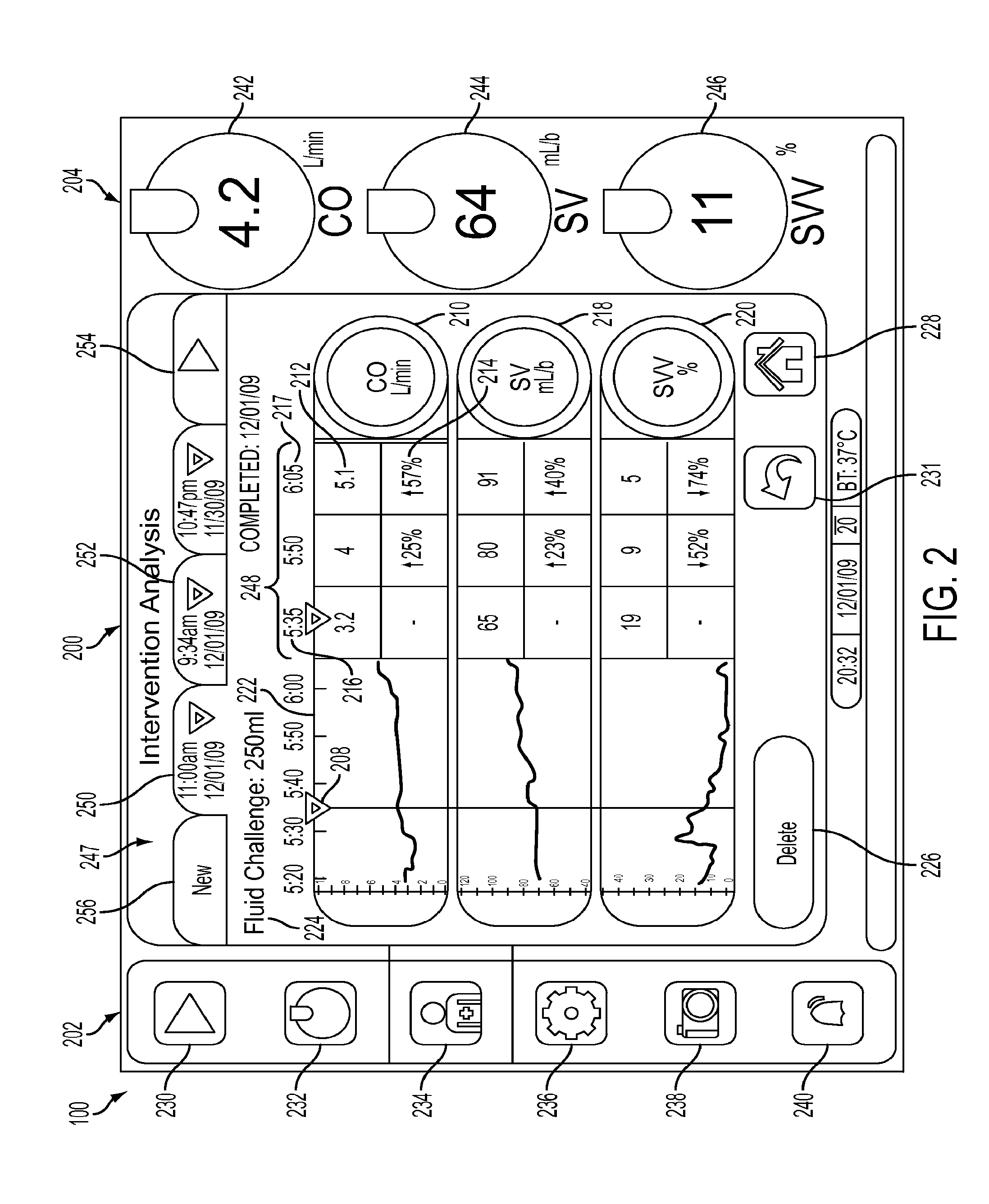
[0044]Apparatus, systems and methods that implement the embodiments of the various features of the disclosure will now be described with reference to the drawings. The drawings and the associated descriptions are provided to illustrate some embodiments of the disclosure and not to limit the scope of the disclosure. Throughout the drawings, reference numbers are re-used to indicate correspondence between referenced elements.

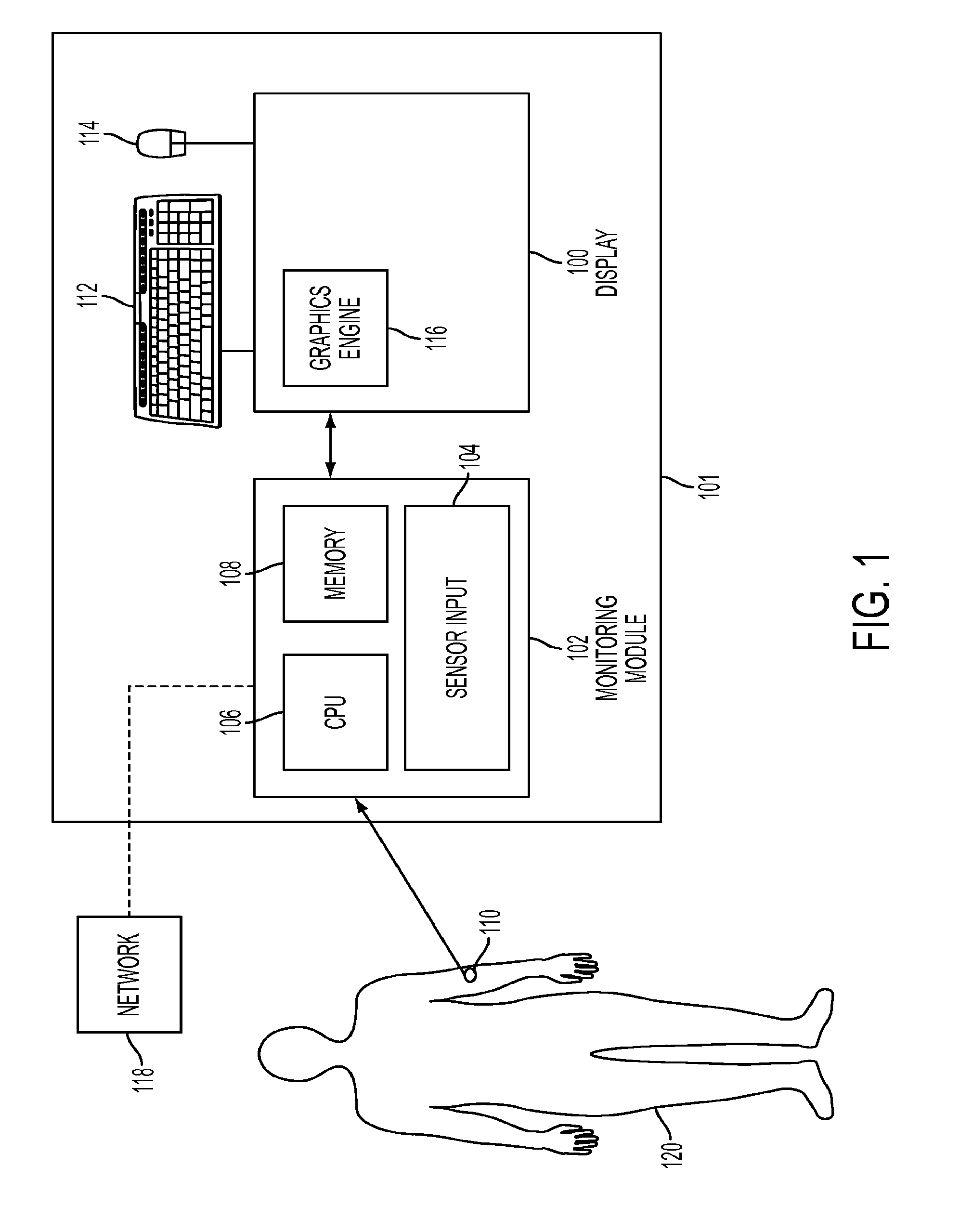
[0045]FIG. 1 is a diagram of a patient monitoring system 101 according to an embodiment of the disclosure. The patient monitoring system 101 includes at least one sensor 110 attached to a patient 120. In a preferred embodiment, the patient monitoring system 101 is a bed-side system, and can be integrated into an existing drug delivery stand, bedbox, or monitoring system rack. The sensor 110 is coupled to a monitoring module 102. The monitoring module 102 includes a central processing unit (CPU) 106, a memory 108, and sensor input circuitry 104. In an embodiment, t...


PUM


Abstract

The disclosure generally relates to a patient monitoring and display system. The system allows a clinician to trigger the occurrence of a clinical event, and record a patient's status following the clinical event. The system calculates and displays a change in a patient's status resulting from the clinical event. The system allows multiple parameters to be tracked and displayed on a single screen. The system can also display various animated organs, such as a heart or a lung, corresponding to an operation of the organs in the patient.

Description

CROSS-REFERENCE TO RELATED APPLICATIONS[0001]This application claims the benefit of U.S. Provisional Patent Application Ser. No. 61 / 222,101, entitled “SYSTEMS AND METHODS FOR MONITORING A PATIENT STATUS IN RESPONSE TO A CLINICAL EVENT,” filed Jun. 30, 2009, and to U.S. Non-Provisional application Ser. No. 13 / 380,015, entitled “SYSTEMS AND METHODS FOR MONITORING AND DISPLAYING A PATIENTS STATUS,” filed Dec. 21, 2011, and to U.S. Non-Provisional application Ser. No. 13 / 544,619, entitled “SYSTEMS AND METHODS FOR MONITORING AND DISPLAYING A PATIENTS STATUS,” filed Jul. 9, 2012,the entire contents of which are incorporated herein in their entirety.BACKGROUND[0002]1. Field[0003]The disclosure relates to monitoring vital signs of a patient, and more particularly to systems and methods for monitoring and displaying a patient's status.[0004]2. Related Art[0005]Devices for measuring various physiological parameters, or “vital signs,” of a patient, such as temperature, blood pressure, heart ra...

Claims


Application Information

Patent Timeline
Patent Type & Authority Applications(United States)
IPC IPC(8): A61B5/00
CPCA61B5/742A61B5/0205A61B5/021A61B5/7435A61B5/4878G16H40/63A61B5/743G16Z99/00A61B5/7275A61B5/4848A61B5/7282A61B5/339A61B5/0022A61B5/029A61B5/08A61B5/7475
Inventor MCKEOWN, MORGANMICHARD, FREDERICDE JONGHE, IVESROTELIUK, LUCHYFRAZIER, JOHNGLINES, ERINDOORISH, SHANEPATTON, DOUG
Owner EDWARDS LIFESCIENCES CORP
Why Eureka
Try Eureka