Method and system for the installation of fault circuit indicators on an electrical feeder

a fault circuit indicator and feeder technology, applied in the direction of fault location by conductor type, circuit arrangement, instruments, etc., can solve the problems of multiple fault locations inability to differentiate between permanent and temporary faults, and extra time for the line crew, so as to maximize the efficient placement of fault circuit indicators and maximize the effect of efficient placement of fcis

Active Publication Date: 2013-12-05
BALTIMORE GAS AND ELECTRIC
View PDF1 Cites 28 Cited by
  • Summary
  • Abstract
  • Description
  • Claims
  • Application Information

AI Technical Summary

Benefits of technology

[0007]An object of the present invention is to provide a method for maximizing efficient placement of Fault Circuit Indicators (FCIs) on an electrical feeder, comprising the steps of obtaining a data set associated with faults on an electrical feeder (wherein said data set includes overhead and underground fault response information) and identifying the number of FCIs and a location of each FCI on the feeder utilizing information contained in the data set. The information contained in the data set includes, but is not limited to, at least one of overhead, underground fault response information, and probabilities of overhead and underground faults in the feeder, wherein said number of FCIs and location each FCI results in a reduction of customer average outage time (AOT) for the feeder.
[0008]Another object of the present invention is to provide a computer program product comprising a non-transitory computer readable medium encoding a computer program for executing on a computer system to provide a computer process for maximizing efficient placement of FCIs on an electrical feeder; the computer process executed by the computer system comprises. The compute process executed by the program consists of several steps. The first step is to obtain a data set associated with faults on an electrical feeder, wherein said data set includes overhead and underground fault response information. The second step is to identify a number of FCIs and a location of each FCI on the feeder utilizing information contained in the data set, wherein said information comprises at least one of overhead, underground fault response information, and probabilities of overhead and underground faults in the feeder, wherein said number of FCIs and location each FCI results in a reduction of customer average outage time (AOT) for the feeder.
[0009]Another object of the present invention is to provide a system for maximizing efficient placement of Fault Circuit Indicators (FCIs) on an electrical feeder. The system has a data management module configured to store a data set, and a FCI placement module configured to process feeder data and identify a number of FCIs and a location of each FCI on the feeder utilizing information contained in the data set, wherein said information comprises at least one of overhead, underground fault response information, and probabilities of overhead and underground faults in the feeder, wherein said number of FCIs and location each FCI results in a reduction of customer average outage time (AOT) for the feeder.

Problems solved by technology

In addition, these devices did not differentiate between permanent and temporary faults.
This procedure can take extra time and in some instances can result in multiple fault locations for the line crew to patrol.

Method used


Image

  • Method and system for the installation of fault circuit indicators on an electrical feeder
  • Method and system for the installation of fault circuit indicators on an electrical feeder
  • Method and system for the installation of fault circuit indicators on an electrical feeder

Examples


Embodiment Construction

[0013]The invention summarized above may be better understood by referring to the following description, which should be read in conjunction with the accompanying drawings and claims. This description of an embodiment, set out below to enable one to practice an implementation of the invention, is not intended to limit the preferred embodiment, but to serve as a particular example thereof. Those skilled in the art should appreciate that they may readily use the conception and specific embodiments disclosed as a basis for modifying or designing other methods and systems for carrying out the same purposes of the present invention. Those skilled in the art should also realize that such equivalent assemblies do not depart from the spirit and scope of the invention in its broadest form.

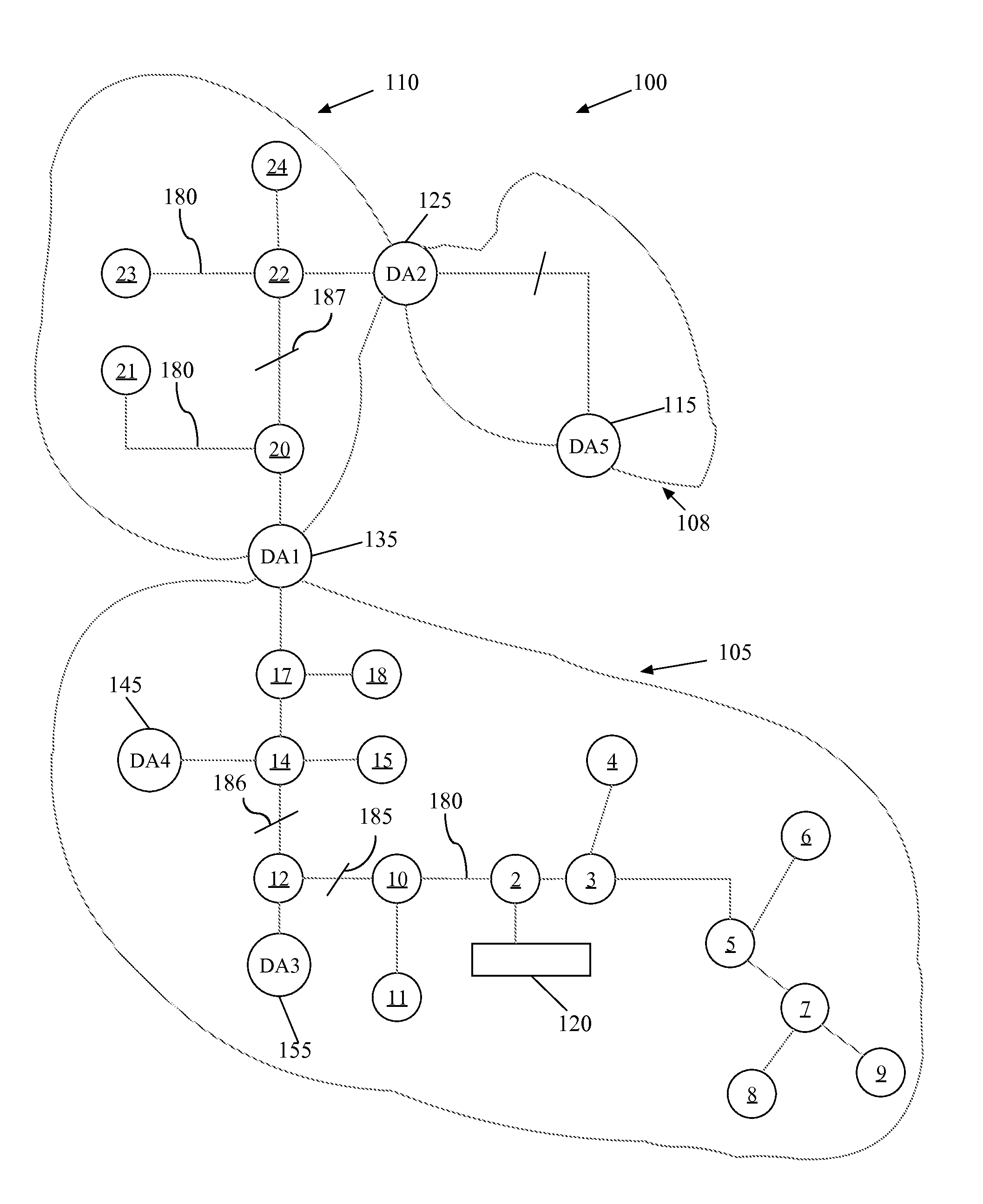
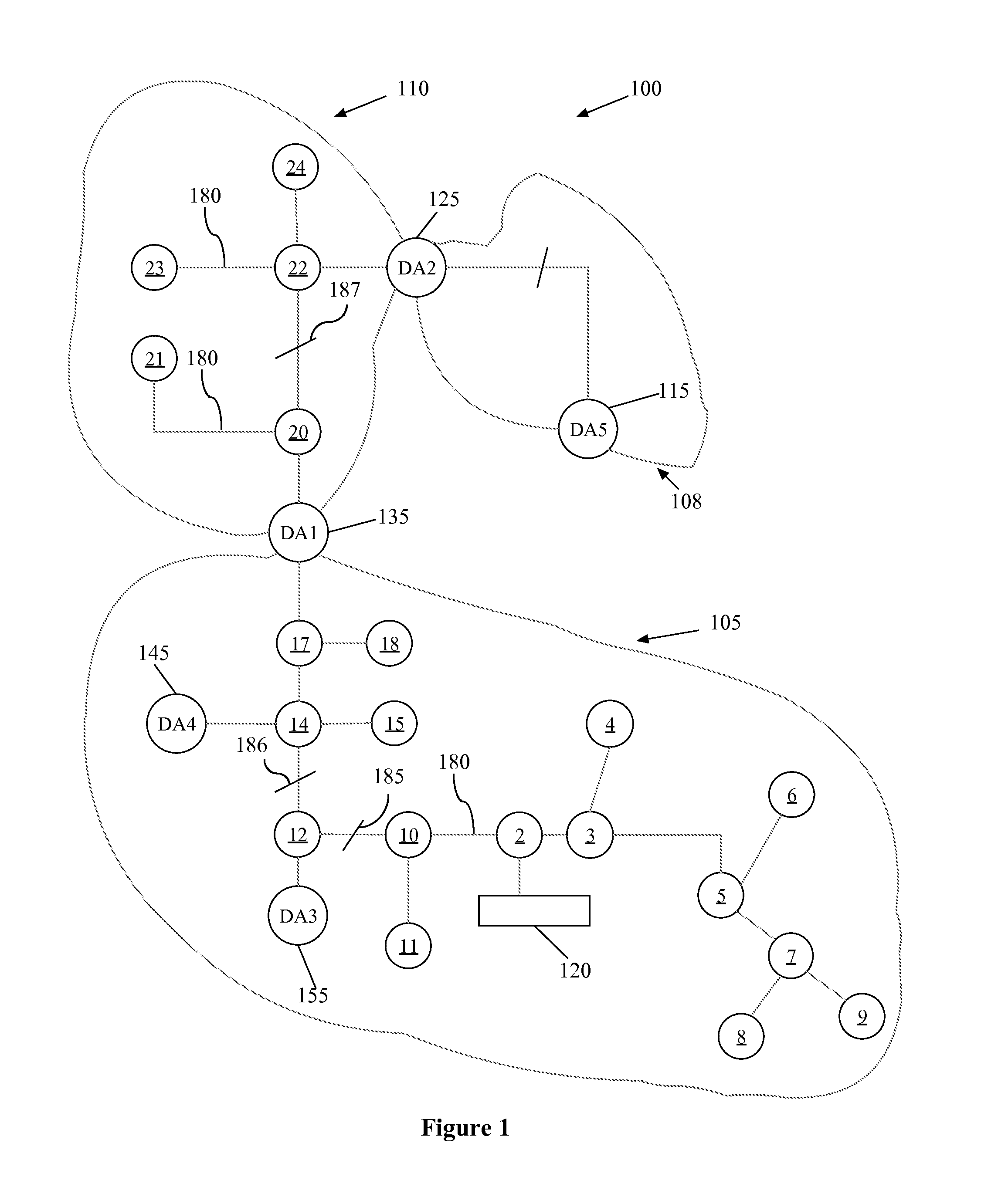
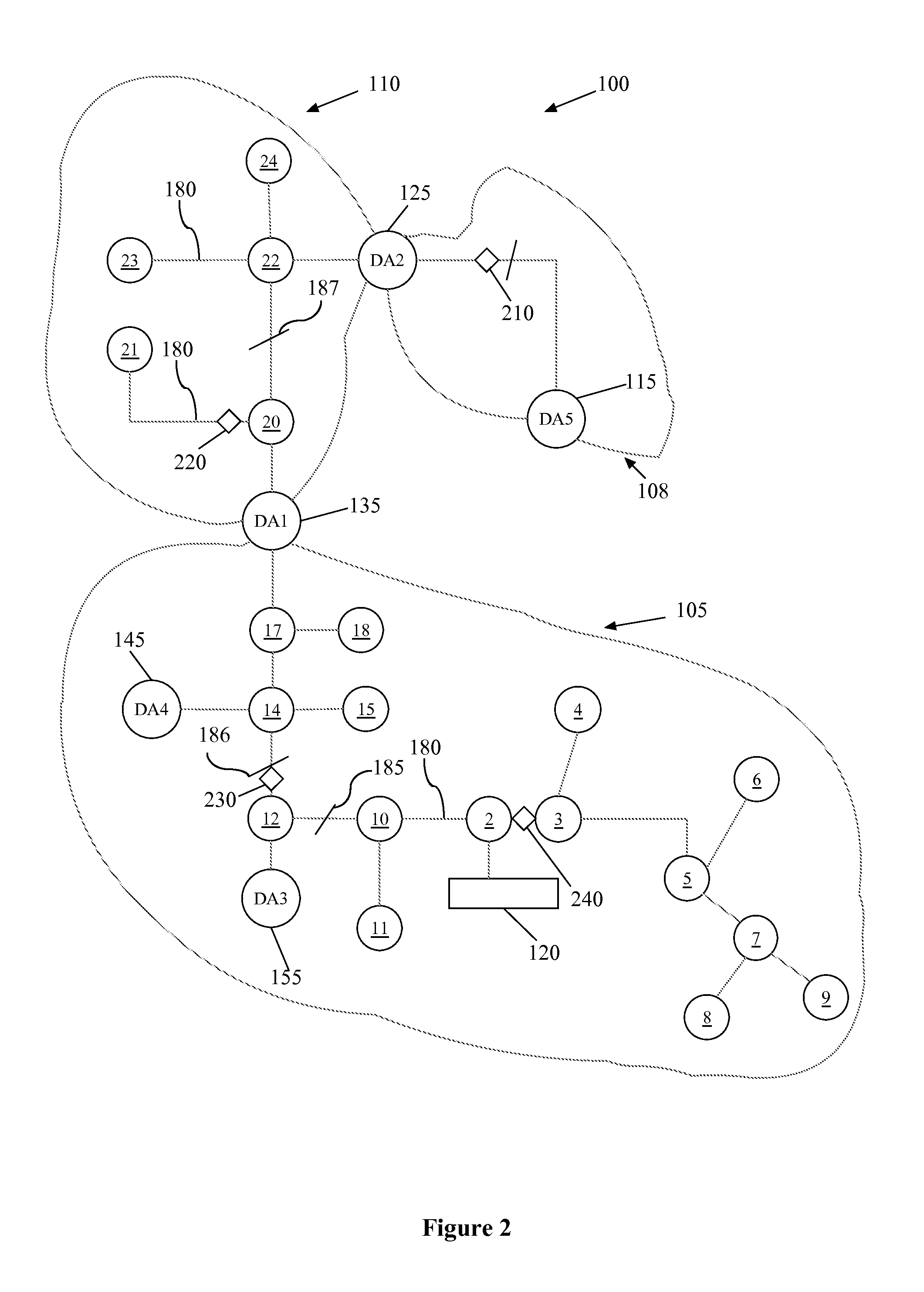
[0014]As provided in this application, an “electrical distribution network” is a system comprising a series of elements that facilitate delivery of electricity to consumers. The elements of the electrical d...


PUM


Abstract

A method for maximizing the benefits of Fault Circuit Indicators on an electrical feeder has two steps. In the first step a data set for the feeder is obtained based on historical data. In the second step, the number of FCIs and their location is calculated based on the data set obtained in the first step. The number of FCIs and their location is determined utilizing a simulation algorithm that ensures each FCI is used efficiently and provides actionable information to the utility's crew.

Description

BACKGROUND[0001]1. Field of the Invention[0002]The invention disclosed herein relates generally to fault circuit indicators (“FCIs”) and more particularly to methods, systems, and processes to maximize the benefits of FCIs on an electrical distribution network.[0003]2. Background of the Invention[0004]FCIs have been part of electrical utility distribution networks for few decades. After the fault occurrence, utility personnel normally patrol and inspect the FCIs for visual identification that the fault has been detected by the devices. The majority of the existing FCIs installed during the past few decades did not have any communication device associated with them. Thus, the utility's back office did not have any indication of the location of a fault until the crew visually inspected every device. In addition, these devices did not differentiate between permanent and temporary faults.[0005]The advances in technology and communications have resulted in development of new FCIs with ad...

Claims


Application Information

Patent Timeline
Patent Type & Authority Applications(United States)
IPC IPC(8): G06F15/00
CPCG01R31/086Y04S10/522Y04S10/40H02J13/001H02J13/00001H02J13/00034Y04S10/52
Inventor VUKOJEVIC, ALEKSANDARFREY, PAUL
Owner BALTIMORE GAS AND ELECTRIC
Why Eureka
Try Eureka