Thermal therapy system and method of use

Inactive Publication Date: 2013-12-12
RHMD
View PDF6 Cites 76 Cited by
  • Summary
  • Abstract
  • Description
  • Claims
  • Application Information

AI Technical Summary

Benefits of technology

[0011]In another aspect of an exemplary thermal therapy system, the joint conforming wrap includes a first chamber for housing an inflatable member such as a bladder and a second chamber for housing one or more N-P Stack/thermoelectric modules therewithin. The thermoelectric modules may be made from alternating p-type and n-type semiconductor elements connected by metallic connectors. Charge flows through the n-type element, crosses a metallic interconnect, and passes into the p-type element. If a power source is provided, the thermoelectric module may act as a cooler/heater, this known as the Peltier effect but may also employ other effects

Problems solved by technology

Acute injuries to joints are sudden, sharp, traumatic injuries that occur immediately (or within hours) and cause pain (possibly severe pain).
Chronic injuries to joints, on the other hand, can be subtle and slow to develop.
They often cause dull pain or soreness and are often the result of overuse.
While this approach is simple and can be economical, it has its own complications including minimal re-usability of the elastic bandage, short life span until the ice melts and non-uniform application of cold and compression due to gradual warming of the fluid in the vicinity of the patient and irregular distribution of ice in the bag.
Further, these systems are subject to leakage and can only supply a c

Method used


Image

  • Thermal therapy system and method of use
  • Thermal therapy system and method of use
  • Thermal therapy system and method of use

Examples


Embodiment Construction

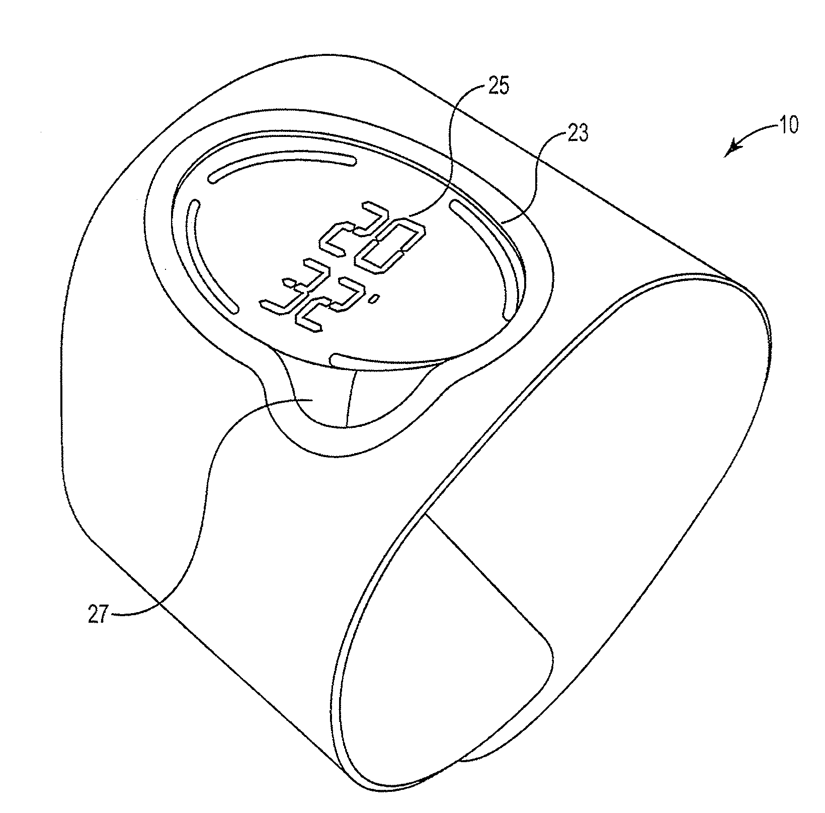
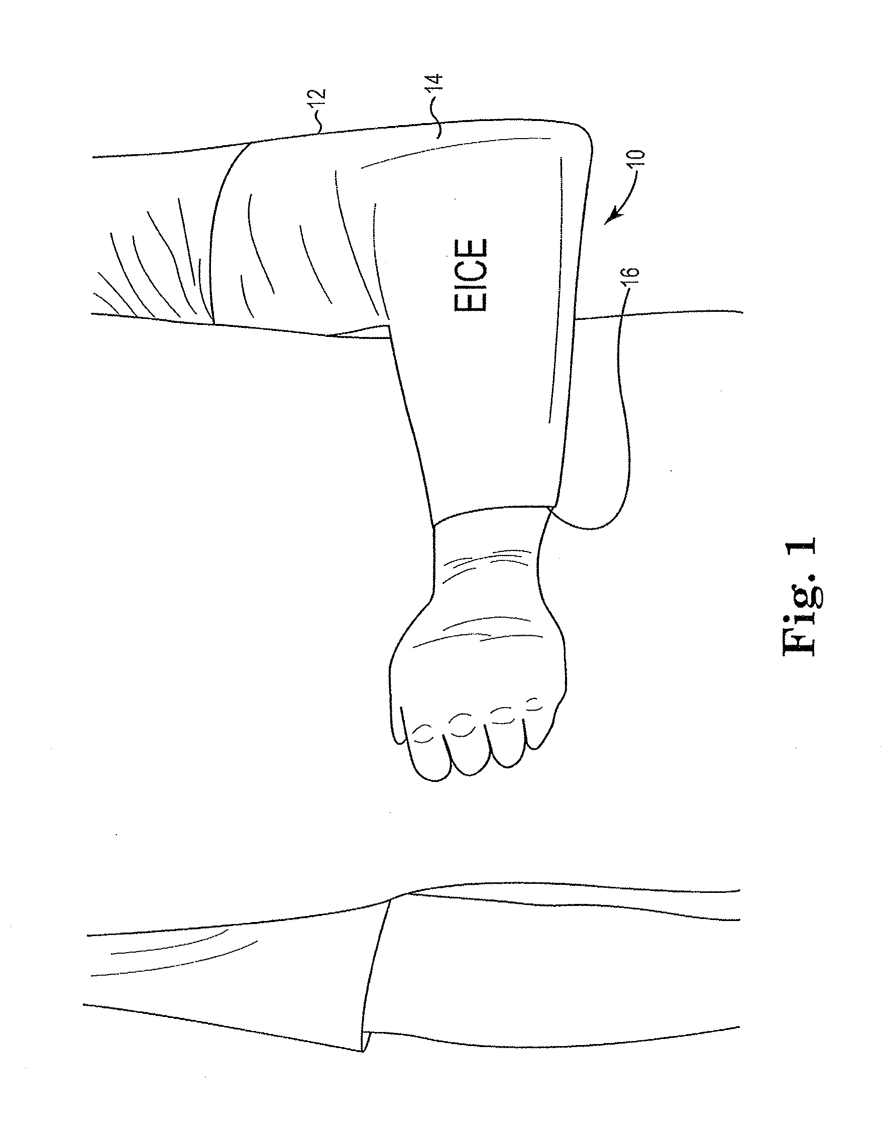
[0037]Referring now to FIG. 1, a joint conforming compression wrap 12 for use on an elbow is shown. Those of skill in the art will appreciate that an elbow wrap is shown by way of illustration and not of limitation and that wraps used for ankles, elbows, knees, and hip, for example, are within the intended scope of the invention. The shape, contour and construction of the wrap will depend on the specific joint covered. The wrap will circumferentially surround, either wholly or in part, the particular joint needing therapy and includes a first outer surface 14 and a second skin contacting surface 16. Those of skill in the art will appreciate that the wrap 12 may be entirely elastomeric, such as a woven elastic material, or may include a hard shell, such as a polycarbonate, with a soft lining.

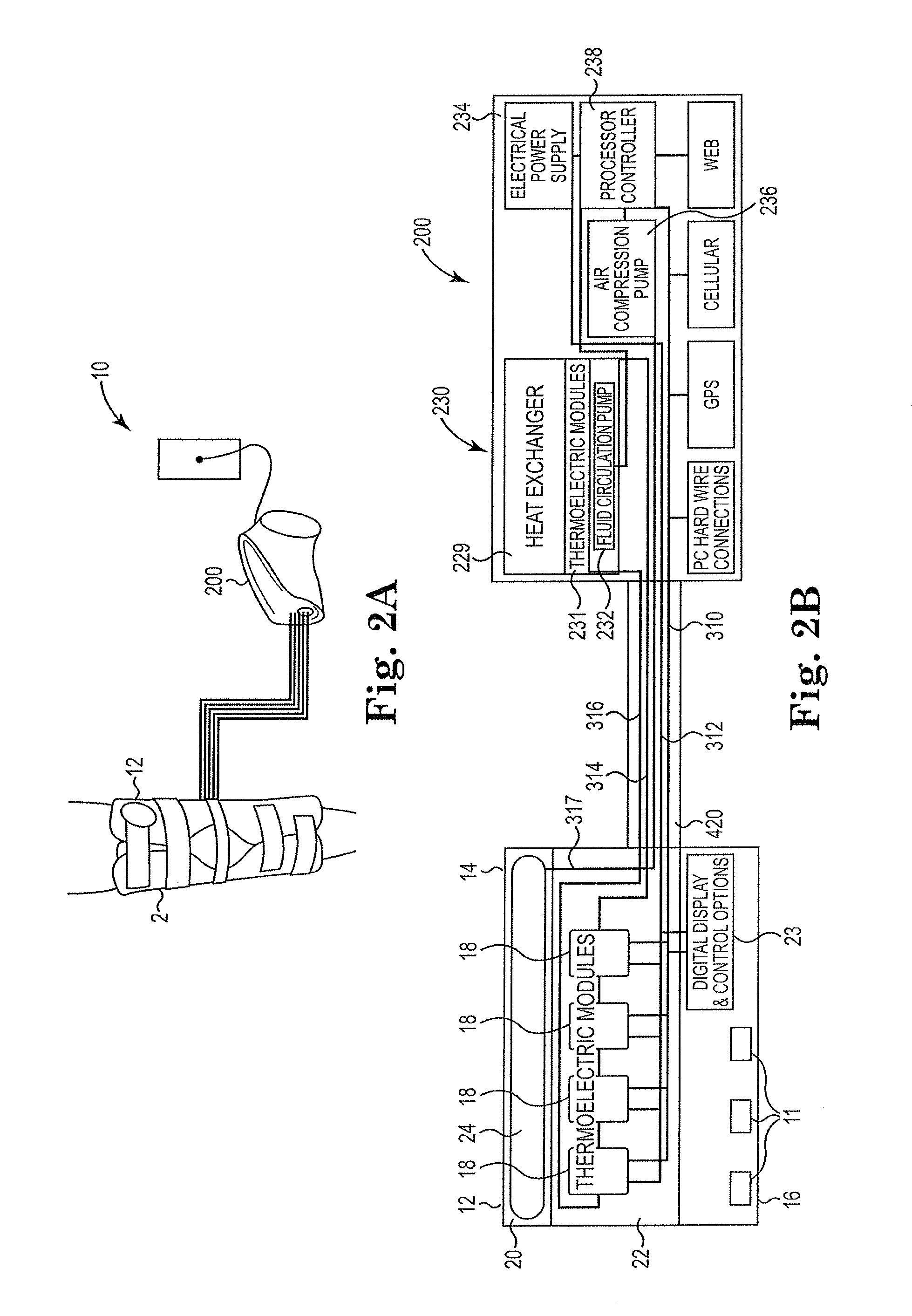
[0038]The joint conforming wrap may be encased in a hard case or soft case that is removably coupled to or permanently attached to the power supply module as best seen in FIGS. 2A and 3A. The joi...


PUM


Abstract

A system that can be used to provide highly controlled thermal therapy and compression to both cool and heat a skin surface and a joint and surrounding tissue below the skin surface is provided. The system includes a joint conforming wrap; a power supply module for supply power to the joint conforming wrap and a cable operably coupling the wrap and the power supply module. The joint conforming wrap and power supply module include opposing thermoelectric modules. The joint conforming wrap is designed to provide heat transfer processes to the body of a patient to warm or cool the skin and a joint and surrounding tissue disposed under the skin.

Description

RELATED APPLICATION DATA[0001]This application is a non-provisional of U.S. application Ser. No. 61 / 658,028, filed on Jun. 11, 2012, the entirety of which is incorporated herein by reference.FIELD OF THE INVENTION[0002]The present invention relates to the cooling and / or heating of a skin surface and a joint and surrounding tissue below the skin surface to alleviate pain. More specifically, the present invention relates to an apparatus that can be used to provide highly controlled thermal therapy and compression to both cool and heat a skin surface and a joint and surrounding tissue below the skin surface.BACKGROUND OF THE INVENTION[0003]Injury to joints and the surrounding tissue may result from a variety of activities such as for example surgery and sports injuries. Acute injuries to joints are sudden, sharp, traumatic injuries that occur immediately (or within hours) and cause pain (possibly severe pain). Most often acute injuries result from some sort of impact or trauma such as ...

Claims


Application Information

Patent Timeline
IPC IPC(8): A61F7/00
CPCA61F7/007A61F2007/0029A61F2007/0039A61F2007/0054A61F2007/0075A61F2007/0096A61F2007/0091
Inventor LEE, MARTINKELLEY, CRAIGBIOLCHINI, ROBERTSTOKES, STEVEN
Owner RHMD
Why Eureka
Try Eureka