Integrated heat pipe and its method of heat exchange

a heat exchange pipe and heat exchange technology, applied in indirect heat exchangers, lighting and heating apparatus, stationary conduit assemblies, etc., can solve the problems of poor heat elimination effect, low cost, and major problems of heat elimination, and achieve the effect of increasing heat transfer efficiency

Inactive Publication Date: 2005-03-24
YANG HONGWU
View PDF22 Cites 74 Cited by
  • Summary
  • Abstract
  • Description
  • Claims
  • Application Information

AI Technical Summary

Benefits of technology

[0014] One object of this invention is to make up the shortcomings of background technology and provide an integrated heat pipe that can increase the heat transfer efficiency and that is an integrated heat pipe of complicated shape surface and radial structure for contact heat source and fluid medium heat source.

Problems solved by technology

Therefore, heat elimination has become a major problem that has to be resolved in the course of research and development of electronic products and it is directly related to the property, reliability and cost of electronic products.
Though their cost was low, their heat eliminating effect was not so good and their reliability was low, therefore, they were not able to meet the requirement of the development of computer.
This inlaying method does not produce very good heat elimination effect as the contact thermal resistance of the element connected with interface in the course of heat transfer is so big that the heat pipe cannot play the role of high efficiency heat transfer and the heat eliminating effect is not so good.
In addition, through by welding the heat absorption end of one or several heat pipes on the metal plate and installing a number of fin groups to support heat elimination at the heat elimination end of heat pipe, the contact thermal resistance of the interface can be reduced, the medium of the heat pipe can not be in full contact with the heat source and can not produce very good heat transfer effect.
However, because of the interface thermal resistance between the casting mould and the wall of heat pipe and the limitations of the structure it is impossible for the original structure to meet the even higher cooling speed requirement of alloy including fast solidifying alloy on the mould and it is more so of certain special and higher requirement.
Because of the limitations of the traditional heat transfer mode and the structure of the base the contact area between base and cooling liquid is small (normally, the area of the heat absorption end is always bigger that that of the heat elimination end) and contact thermal resistance is big, it is difficult for the cooling liquid to carry away the large amount of heat emitted by the melt during the solidification process instantly.
Therefore, it is very difficult to improve and balance the distribution of temperature field so as to further increase the heat transfer speed during the solidification process.
Moreover, as the temperature at the heat balance spot of the base is fairly high during operation, the capacity of the production unit declines, its life gets shorter, its efficiency gets lower and the quality deteriorates.
As the high temperature heat flux flows through nozzle for such a long time during operation that the nozzle is easily damaged, people tend to manufacture nozzles with metals of fine thermal conductivity and some even cool nozzles with water.
Notwithstanding all this, the effect is not so good and the life does not get any longer and the cooling water leakage may damage the electrical insulation of the equipment greatly reducing the reliability of the equipment.
Although some people use heat pipe technology in nozzles, the high efficiency heat transfer characteristic of heat pipe can not be displayed because their technical design fails to greatly improve the heat elimination area of nozzle and the geometric dimensions of nozzle are small.
Therefore, the existing technology is still unable to meet the requirement of the engineering technology and should be further improved.
Nevertheless, the branch like distribution of the heat pipe of the traditional heat pipe heat exchanger and its square box structure is apt to fouling on heat elimination surface and dead corner and whirlpool of fluid flow thus affecting the normal heat exchange and application life of heat exchanger.
The single structure and huge volume of the traditional heat exchanger is one of the limiting factors.
If the heat including that emitted inside the rotor cannot be eliminated, overheating might happen reducing the power, abating the insulation and damaging electrical and mechanical equipment, or even leading to the loss of working capacity of equipment.
However, the above-mentioned methods have many shortcomings, such as inferior heat elimination and high production cost and still they have a common shortcoming, that is, heat elimination area is small and the heat elimination capacity is intrinsically inadequate.
All these have greatly limited the application and popularization of heat pipe and heat pipe technology.
Particularly, as to how to reduce thermal resistance of contact heat source apart from the heat flux to increase heat transfer efficiency, it is difficult for the existing heat pipe heat exchange technology to display its merit fully because of its unique structure.

Method used


Image

  • Integrated heat pipe and its method of heat exchange
  • Integrated heat pipe and its method of heat exchange
  • Integrated heat pipe and its method of heat exchange

Examples


application example 1

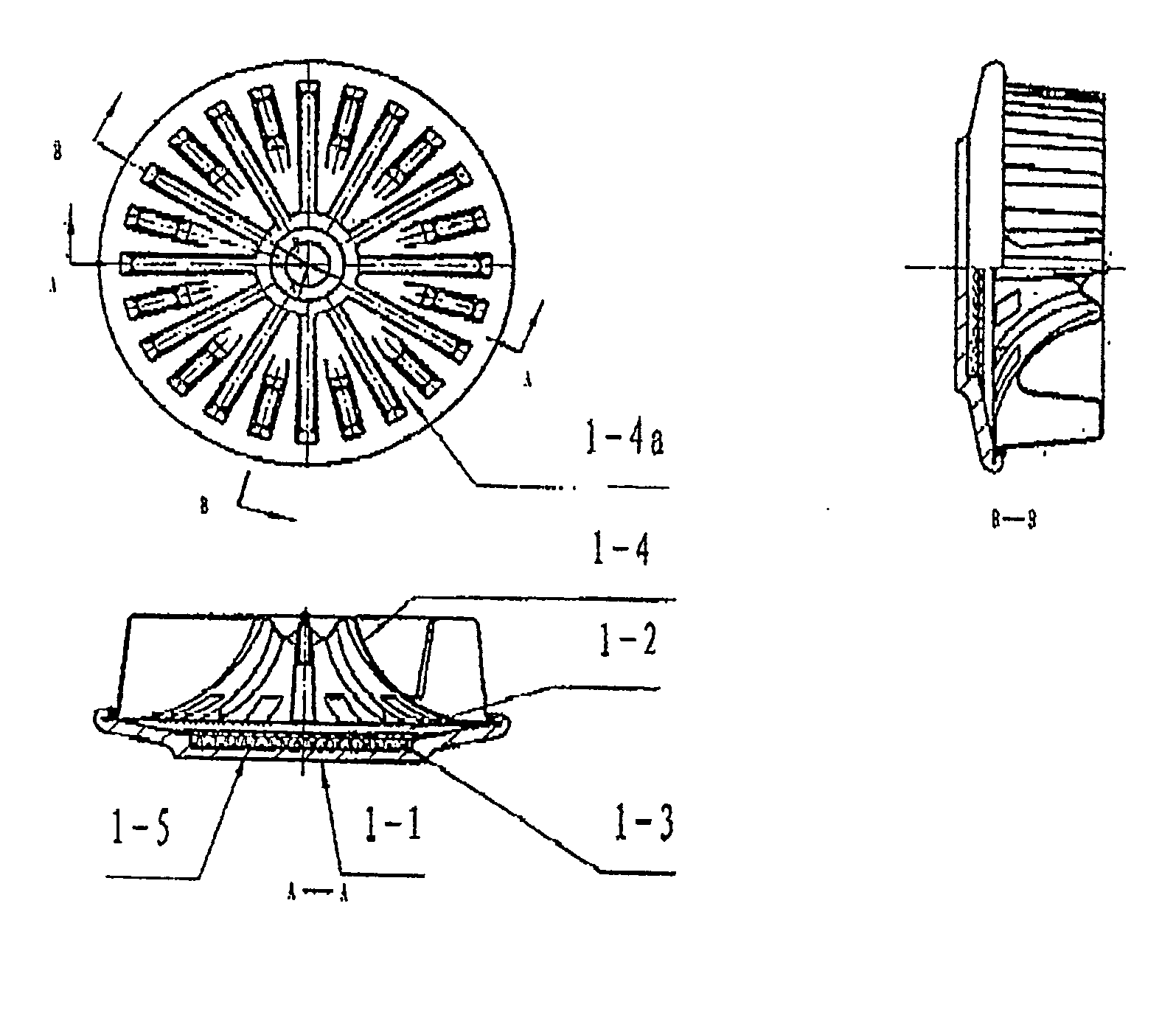
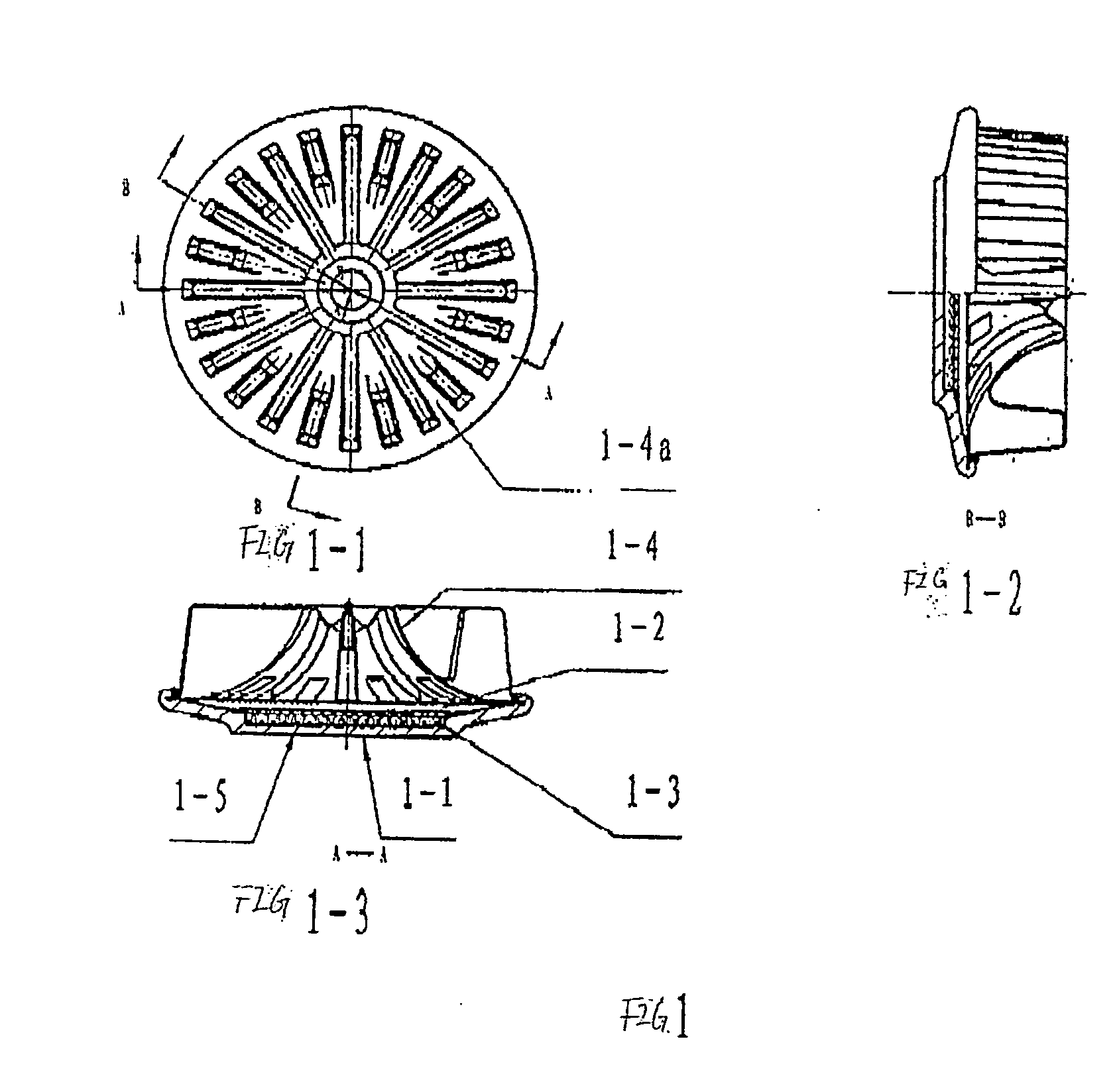
[0080] As shown in FIG. 1, Application Example 1 is a kind of heat pipe applicable to integrated heat pipe coolers with an in-line finned structure for cooling CPU of computers, express cards, high-power power electronic components.

[0081] It is a kind of integrated heat pipe composed of a shell 1-1 with an enclosed chamber 1-2, featuring a heat carrier on the outer side of the enclosed vacuum chamber; the heat carrier 1-4 has a thin-wall fluid passage 1-4a with radial in-line distribution of 12 long fins and 12 fins matching with the axis of the heat pipe, the inner side of each group of long fin and short fin is the internal chamber of the heat carrier 14, and is connected with the vacuum chamber 1-2 and the extension to the vacuum chamber 1-2; the outer side of each long fin and short fin is cooling surface of the fluid passage 1-4a of the heat carrier 1-4, which contacts with the cool fluid; each group of the heat carrier shares an enclosed chamber 1-2 and the heat transfer medi...

application example 2

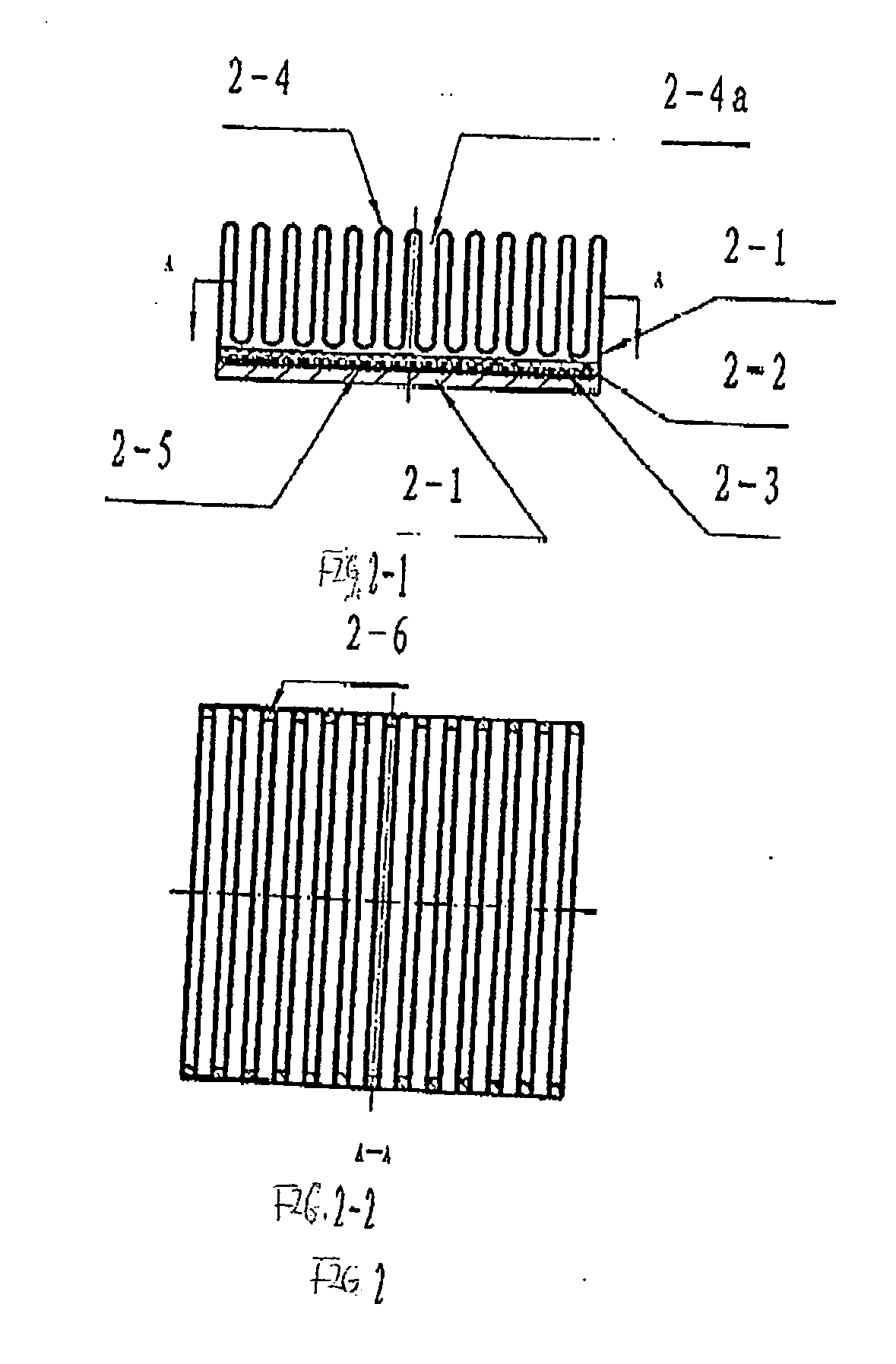
[0084] As shown in FIG. 2, Application Example 2 is a kind of integrated heat pipe applicable to integrated heat pipe coolers with an in-line finned structure for cooling CPU of computers, or high-power power electronic components.

[0085] It is a kind of integrated heat pipe composed of a shell 2-1 with an enclosed chamber 2-2 that is vacuumed to fill in a heat transfer medium 2-3. It features a heat carrier 2-4 on the outer side of the vacuum chamber 2-2; The heat carrier 2-4 has a fluid passage 2-4a structure with parallel array of 13 groups of finned thin-wall fluid passage 2-4a from heat-in of the shell to its opposite end; the internal side of each group of finned thin-wall fluid passage 2-4a is the inner chamber of the heat carrier and is connected with the enclosed vacuum chamber 2-2 and an extension to the enclosed vacuum chamber 2-2; the outer side of each group of finned thin wall fluid passage 2-4a is the cooling surface of the heat carrier 2-4, which contacts with the co...

application example 3

[0088] As shown in FIG. 3, Application Example 3 is a kind of heat pipe applicable to integrated heat pipe coolers with a thin-wall rectangle pipe structure for cooling CPU of computers, or high-power power electronic components.

[0089] It is a kind of integrated heat pipe composed of a shell 3-1 with an enclosed chamber 3-2 that is vacuumed to fill in a heat transfer medium 3-3. It features 11 groups of heat carrier 3-4 in the inner side of the enclosed vacuum chamber 3-2 that is enclosed by the rectangle shell, and the left and right end plates 3-6 of the shell; the heat carrier is a fluid passage 3-4a structure composed of thin-wall pipes with a rectangle cross section and runs through both ends of the end plates 3-6 of the shell; the outer wall of each thin-wall pipe with rectangle cross section constitutes the inner chamber of the heat carrier 3-4 and is connected with the enclosed vacuum chamber 3-2 and inside the enclosed vacuum chamber 3-2; the inner wall of each rectangle t...


PUM


Abstract

The present invention relates to a kind of integrated heat pipe and a method of heat exchange. The heat pipe includes a tank (1-2) as a heating potion and a lot of heat carriers (1-4) as a radiating portion. The tank (1-2) and the heat carriers (1-4) have same cavity in which a coolant (1-3) is partially filled. The tank (1-2) is held in close contact with a heat source (such as electronic elements). The heat carriers (1-4) are arranged at an interval so that the radiating channels (1-4a) are formed between them. The coolant (1-3) in the tank (1-2) is heated by the heat sources, vaporized coolant moves to the heat carriers (1-4) and condenses in there. According to the invention, the heat pipe can be increased its radiating surface significantly with the varied arrangement of the heat carriers (1-4).

Description

FIELD OF INVENTION [0001] This invention is related to heat exchange technology and method, specifically, an integrated heat pipe and its heat exchange method. BACKGROUND OF THE INVENTION [0002] The development of LSI, mainframe computer and electrical and electronic technologies has imposed higher requirements on the heat elimination of electronic elements and components. For example, the integration level of CPU chips of computers has risen by nearly 20,000 folds just within 30 years with its consumption power rising up to a few dozen watts from its initial a few watts and with the resulting heat flux being up to 100 W / cm2 in some cases. The working reliability and life of computer is closely related to its working temperature and the required maximum temperature (internal) of chips ≦130° C. and the required surface temperature ≦80° C. However, its working reliability will decrease by 3.8% whenever the temperature of chip rises by 1° C., and its life will increase by 50% whenever ...

Claims


Application Information

Patent Timeline
Patent Type & Authority Applications(United States)
IPC IPC(8): F28D1/00F28D15/02
CPCF28D15/0233F28D15/0208F28D15/02
Inventor YANG, HONGWU
Owner YANG HONGWU
Why Eureka
Try Eureka