Light emitting device

a technology of light-emitting devices and light-emitting lamps, which is applied in the direction of semiconductor devices, basic electric elements, electrical appliances, etc., can solve the problems of reducing the light conversion efficiency of the phosphor contained in the light conversion member, generating pressure mercury lamps generate a large amount of heat, so as to prevent the deterioration of the phosphor, improve the light conversion efficiency of the phosphor, and improve the effect of the light-

Active Publication Date: 2009-01-27
NICHIA CORP
View PDF22 Cites 82 Cited by
  • Summary
  • Abstract
  • Description
  • Claims
  • Application Information

AI Technical Summary

Benefits of technology

[0010]Generally, it is known that the light conversion efficiency of a phosphor contained in a light conversion member reduces as the ambient temperature of the phosphor rises. In order to solve the above problem, the aforementioned techniques are devised as a method for eliminating an external heat generation factor of the light conversion member in a light emitting device. That is, a mount substrate of light emitting diode is cooled, or the cooling portion is provided in a side of terminal with a phosphor coated thereon that the phosphor is not coated, to eliminate heat of the light conversion member that is externally received.

Problems solved by technology

However, the high-pressure mercury lamp generates a large amount of heat, and additionally has visible light spectrum.
In this case, dissimilarly to the temperature rise of the whole light conversion member due to heat that is externally applied, the phosphor contained the light conversion member reduces its light conversion efficiency due to its own heat generation.

Method used


Image

  • Light emitting device
  • Light emitting device
  • Light emitting device

Examples


first embodiment

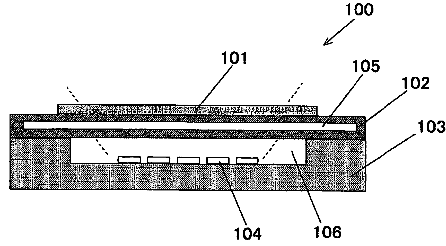
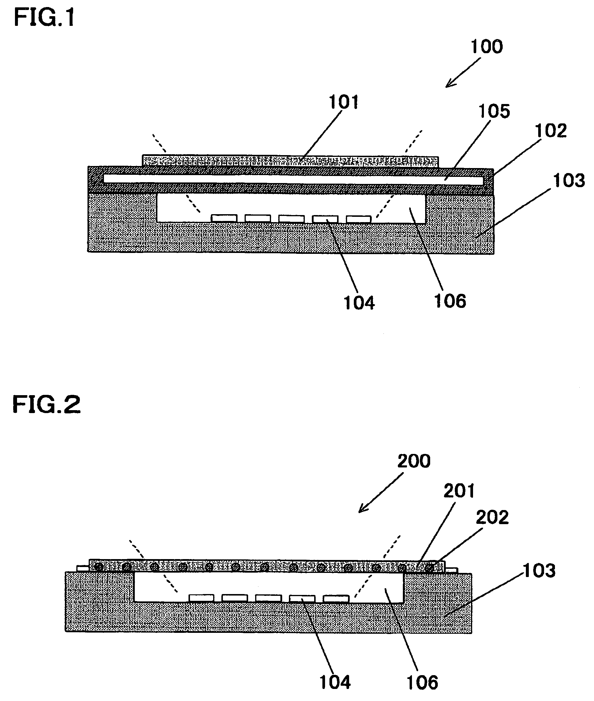
[0088]A light emitting device of a first embodiment of the present invention comprises a light emitting element, a light conversion member including a phosphor material that is capable of absorbing light emitted from the light emitting element at least partially and emitting light in different wavelength, and a heat dissipation member that is located in a side where the light conversion member is provided as viewed from the light emitting element. That is, the light emitting device according to the present invention comprises a semiconductor light emitting element, a light conversion member, and a heat dissipation member, thus, the heat dissipation member aids heat dissipation from the light conversion member containing a phosphor. Accordingly, even in the case where the phosphor is exposed to high power excitation light, since self-heat generation of the phosphor can be suppressed, and deterioration of the phosphor can be prevented, the output of light emitting device does not dete...

second embodiment

[0173]A light emitting device according to a second embodiment has a heat dissipation member having a flow path of a refrigerant includes a first heat dissipation member that has a first flow path in a side where the light emitting element is mounted, and a second heat dissipation member that has a second flow path in a side where light from the light emitting element is incident. The second heat dissipation member includes the light conversion member, in the construction of the light emitting device according to the first embodiment. That is, the light emitting device according to the present invention comprises a water-cooling heat dissipation member that suppress heat conducted from the light emitting device, and the light conversion member containing the phosphor that is provided thereon. Accordingly, since self-heat generation of the phosphor can be suppressed, and deterioration of the phosphor can be prevented, the output of light emitting device does not deteriorate. Therefor...

third embodiment

[0192]A light emitting device of a third embodiment of the present invention comprises a heat dissipation member that is formed of two plate-shaped members that form a flow path for flowing cooling fluid between them, and a plurality of light emitting elements that are mounted to be two-dimensionally arranged on a main surface of the heat dissipation member, wherein a plurality of protruding portions are formed in the surface of the plate-shaped member inside the flow path, and at least some of the plurality of protruding portions are formed such that their centers are located between the light emitting elements and a substantially central part of the light emitting element. The other construction is similar to the first embodiment unless otherwise noted.

[0193]A heat dissipation member according to the third embodiment is now described.

(Heat Dissipation Member)

[0194]The heat dissipation member (hereinafter, occasionally referred to as a “heat sink”) according to the present inventio...


PUM


Abstract

A light emitting device comprises a light emitting element, and a light conversion member including a phosphor material that is capable of absorbing light emitted from the light emitting element at least partially and emitting light in different wavelength. The light emitting device further comprises a heat dissipation member in a side where the light conversion member as viewed from the light emitting element.

Description

TECHNICAL FIELD[0001]The present invention relates to a light emitting device with a light emitting element such as laser diode (LD) and light emitting diode (LED) mounted therein. More particularly, the present invention relates to a light emitting element with a light emitting element and a phosphor material that absorbs light from the light emitting element as excitation light and emits luminescent radiation of different wavelength. Moreover, the present invention relates to a heat dissipation member used against heat dissipation of a semiconductor light emitting element or a semiconductor photoreceptor element, or a heat generating element such as semiconductor device, and to a semiconductor apparatus having this heat dissipation member.BACKGROUND ART[0002]A lighting apparatus with a number of light emitting diodes mounted on a conductive plate is proposed as a lighting apparatus employing light emitting diodes. For example, in a lighting apparatus shown in Patent Document 1, a ...

Claims


Application Information

Patent Timeline
Patent Type & Authority Patents(United States)
IPC IPC(8): H01L33/00H01L25/075H01L33/50H01L33/64
CPCH01L25/0753H01L33/507H01L33/644H01L33/648H01L2224/48091H01L2924/00014H01L2924/00H01L2924/01322H01L2924/3025
Inventor MURAYAMA, TAKASHITAMAKI, HIROTOTAKEICHI, JUNJI
Owner NICHIA CORP
Why Eureka
Try Eureka