Drilling device and process

Inactive Publication Date: 2013-12-19
BLOOMFIELD JOHN
View PDF8 Cites 3 Cited by
  • Summary
  • Abstract
  • Description
  • Claims
  • Application Information

AI Technical Summary

Problems solved by technology

The drill bits are subject to wear, and eventually, wear out.
As wear progresses, the cutting discs become dull,

Method used


Image

  • Drilling device and process
  • Drilling device and process
  • Drilling device and process

Examples


Embodiment Construction

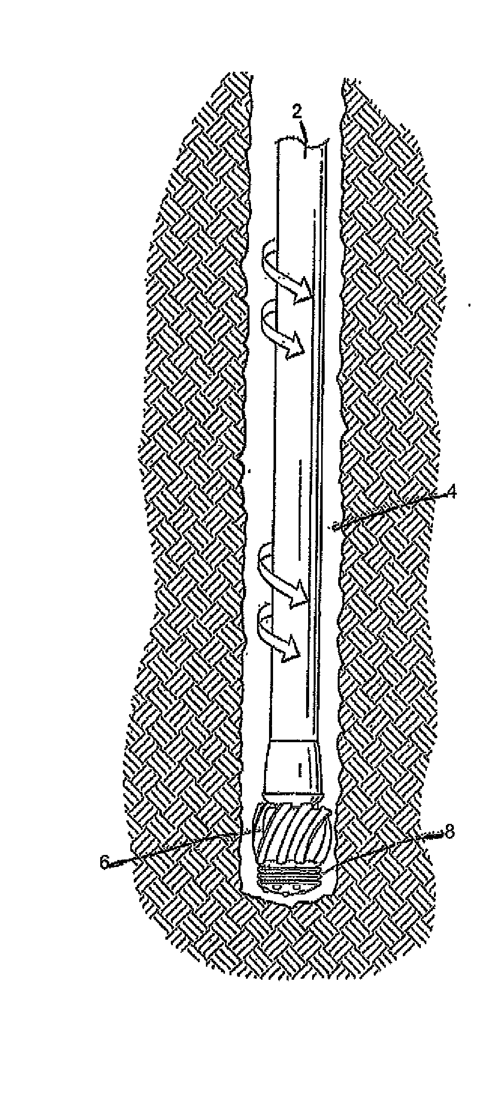
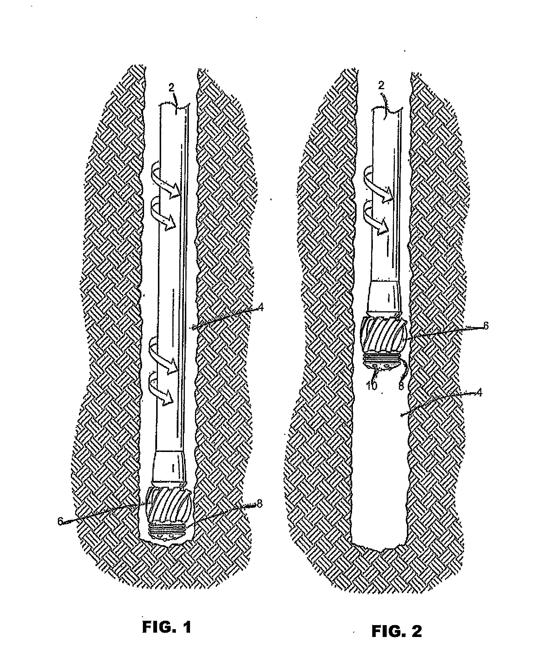
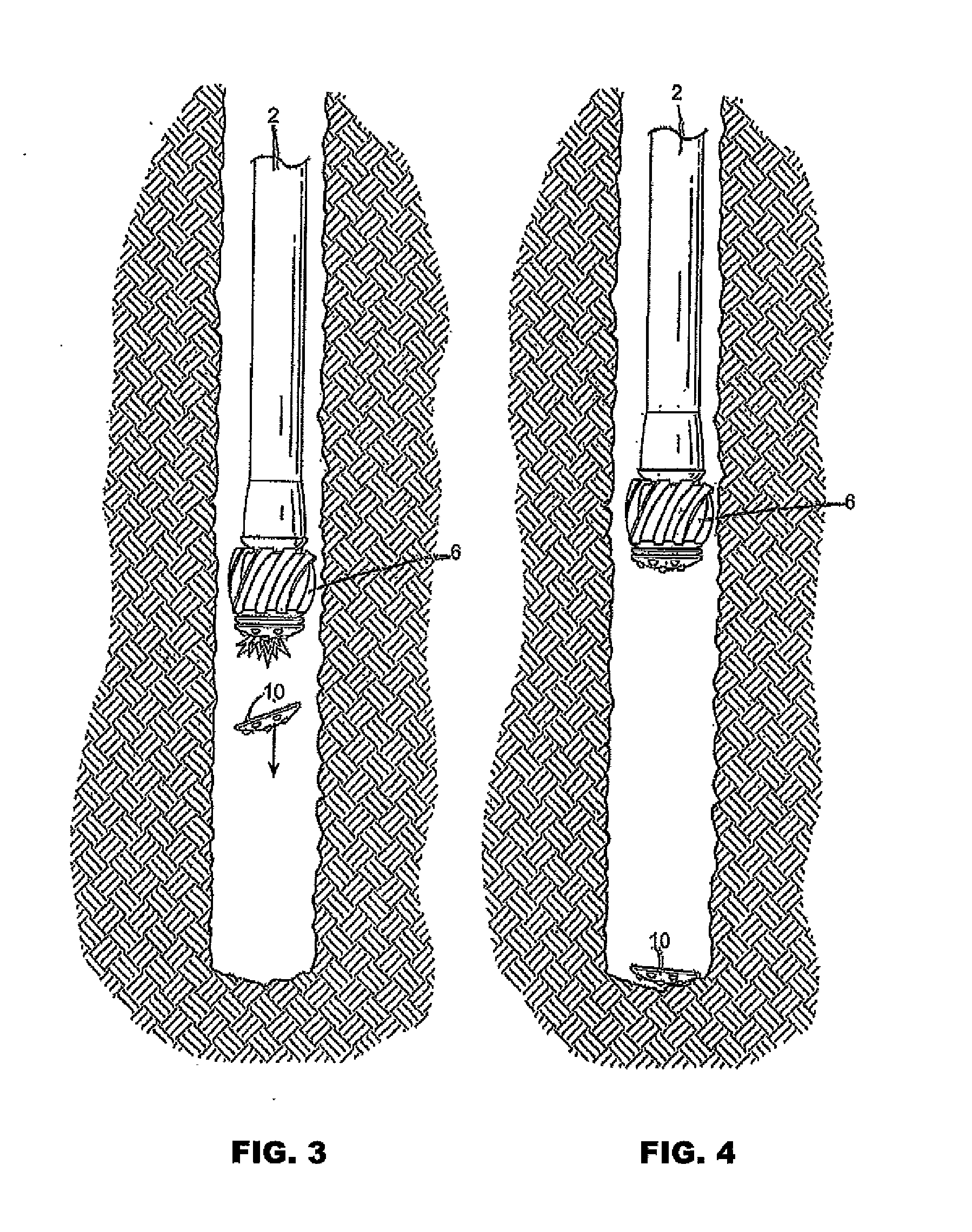
[0019]The drawing figures demonstrate a forward, or distal, end of a drill string with the drill bit assembly comprised of a mandrel and associated cutting faces. The drill string in use may be of substantial length, and may be thousands of feet long. The drill string is formed by joining multiple sections of pipe. The drawing figures demonstrate only the most forward or distal section of pipe 2, and depict only the last few feet of a hole 4 that may be thousands of feet deep.

[0020]Affixed to the end of the most distal pipe section, and at the most distal end of the pipe section, is a mandrel 6. The most distal end of the mandrel is a plurality of drill cutting faces 8. The drill cutting faces are used to cut away earth, rock, and other geological material. In one embodiment, the cutting faces are formed as a plurality of disks having cutting material 20, such as PCD, embedded therein. The plurality of cutting faces is present sequentially on the mandrel as shown in the drawing figu...


PUM


Abstract

A plurality of cutting faces is attached sequentially at a distal end of a drill string. The forward most cutting face that is distal to the top of the hole is exposed and used for drilling until worn to a point of inefficiency. The forward most or distal cutting face is then detached, exposing the next cutting face in the sequence. Detachment of the forward most cutting face is performed by remote actuation at the top of the drill string and/or outside the hole. A new cutting face is provided without the necessity of removing the drill string. The detachment process is repeated as long as drilling is continued and cutting faces remain.

Description

[0001]The contents of Provisional Application U.S. Ser. No. 61 / 659,677 filed Jun. 14, 2012, on which the present application is based and benefit claimed under 35 U.S.C. §119(e), is herein incorporated by referenceFIELD OF THE INVENTION [0002]This invention relates to drilling of holes in the earth, and is more specifically related to a device and method for changing drill cutting faces of drill strings for use while the drill sting is in situ in the hole.BACKGROUND OF THE INVENTION[0003]Drilling for oil and gas involves a drill bit and hundreds of lengths of pipe. A common drill bit is cast metal or machined housing studded with multiple protrusions. The protrusions comprise a hard surfaced material, which may be a ceramic type material that is fortified with multiple industrial diamonds 20. The resulting cutting discs are known in the industry as polycrystalline diamond (PDC) cutters.[0004]As the bit rotates it cuts through the earthen material. Pipe sections are sequentially join...

Claims


Application Information

Patent Timeline
IPC IPC(8): E21B10/633
CPCE21B10/633E21B7/007
Inventor BLOOMFIELD, JOHN
Owner BLOOMFIELD JOHN
Why Eureka
Try Eureka