Vehicle door closer device

a technology for a vehicle door and a closer, which is applied in the direction of doors, locking applications, gearing, etc., can solve the problem of not providing the release function for moving a ratch

Active Publication Date: 2014-01-02
MITSUI KINZOKU ACT
View PDF36 Cites 25 Cited by
  • Summary
  • Abstract
  • Description
  • Claims
  • Application Information

AI Technical Summary

Benefits of technology

[0006]In view of the disadvantages in the prior art, it is an object of the invention to provide a vehicle door closer device providing both closing function and releasing function and e

Problems solved by technology

The device provides closing function for moving the latch from the half-latch position to the full-latch position, but does not

Method used


Image

  • Vehicle door closer device
  • Vehicle door closer device
  • Vehicle door closer device

Examples


Embodiment Construction

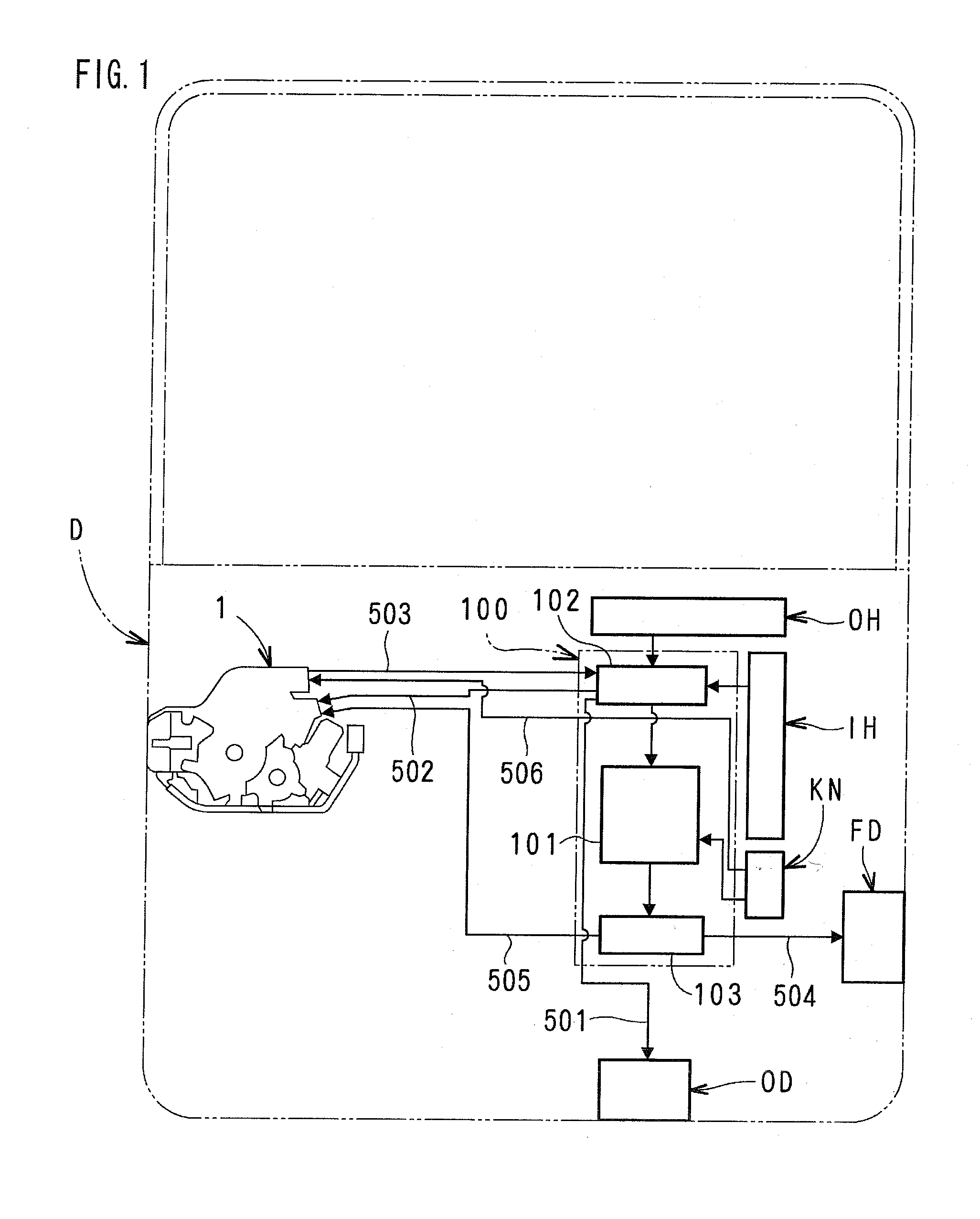
[0023]One embodiment of the present invention will be described with respect to the drawings. In the following description, the left and right sides are deemed as “rear” and “front” of a vehicle respectively inFIG. 1 and FIGS. 7-14.

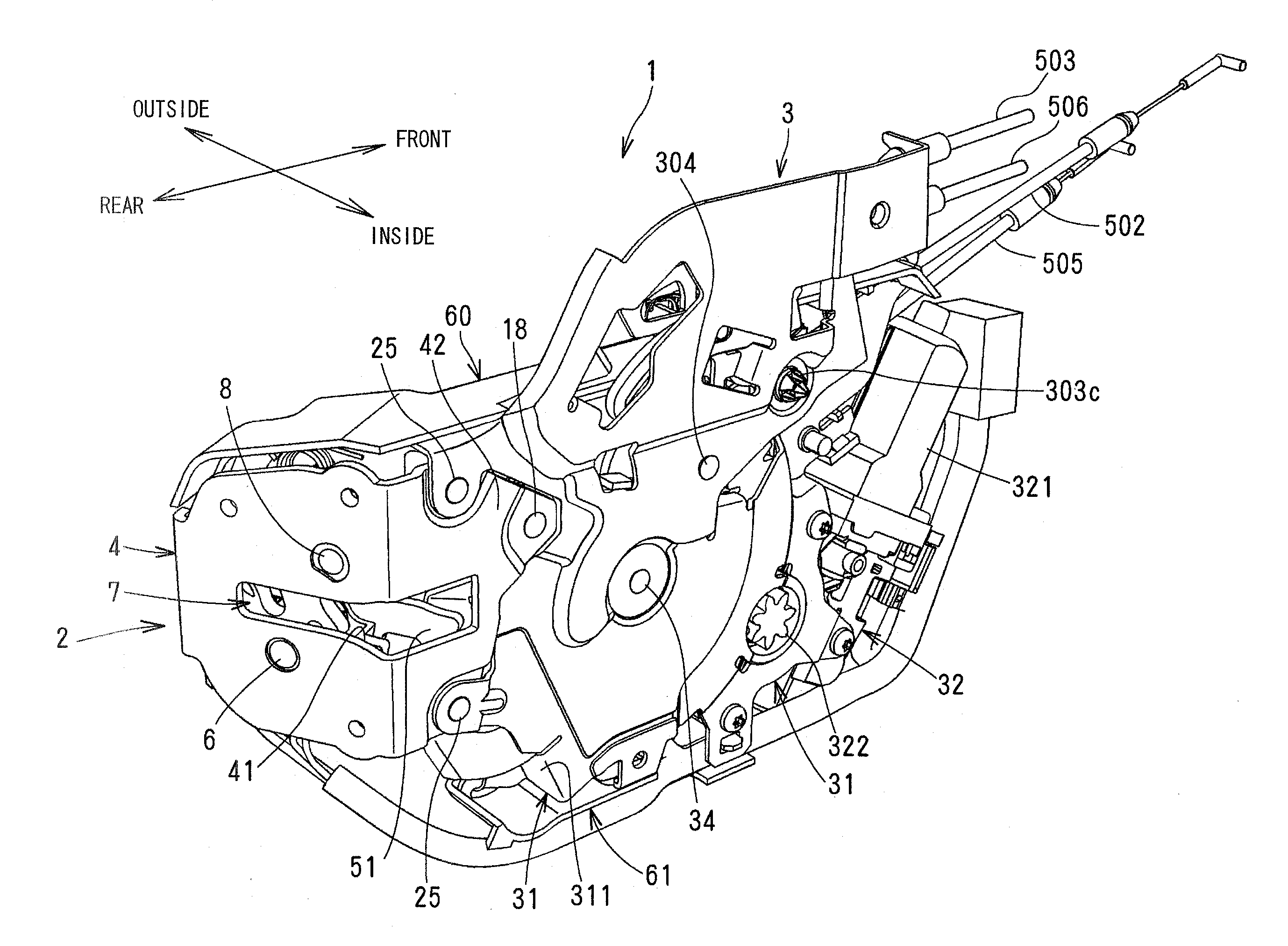
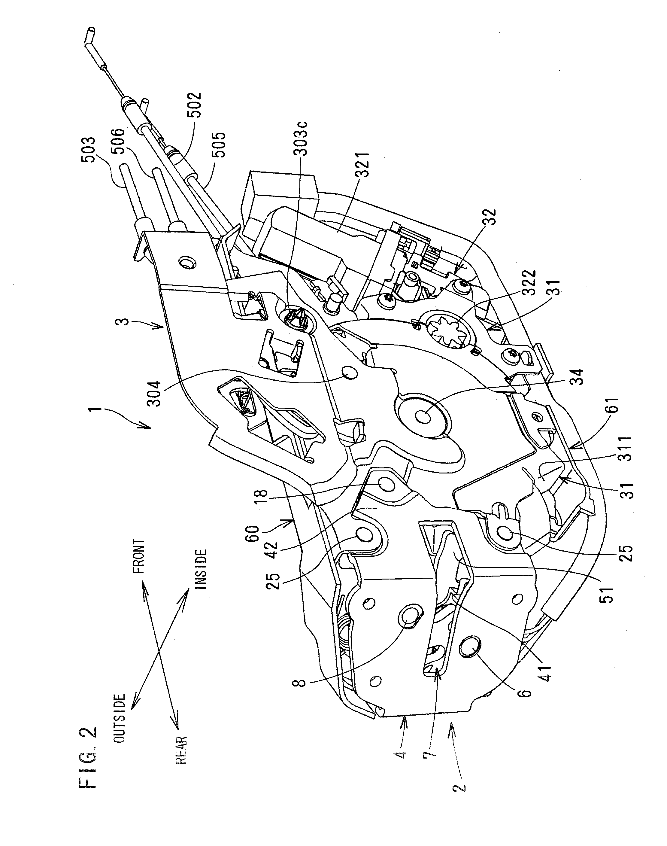
[0024]In FIG. 1, D denotes a sliding door that slides open and closed; OH denotes an outside handle on the outer panel of the door D to open and close the door D; IH denotes an inside handle on the inner panel inside the vehicle; KN denotes a locking knob disposed on the inner panel of the door D to change unlocking and locking of a locking / unlocking mechanism 101 later described; FD denotes a front-door-latch section disposed at the front of the door D to hold the door D closed; OD denotes a fully-open holding latch at the lower end of the door D to hold the door in a fully-open position; 1 denotes a door closer device at the rear of the door D to hold the door D closed with the front-door-latch section FD; and 100 denotes a motion-connecting section dis...


PUM


Abstract

In a planetary gear mechanism of a vehicle door closer device, a planetary gear meshes with a sun gear and a ring gear. When the ring gear turns in one direction, the planetary gear orbits while it turns on its own axis. A closing lever is pivoted on the planetary gear and turns with orbiting of the planetary gear to move the latch to a full-latch position to enable the door to close. When the ring gear turns in the other direction, the planetary gear turns on its own axis and the sun gear turns to allow the ratchet to release from the latch to to enable the door to open.
The planetary gear mechanism slows down a motor and a motion is transmitted to the ratchet to enable the ratchet to release from the latch. When the motor stops, the motion is disconnected to enable the ratchet to return to engagement with the latch.

Description

BACKGROUND OF THE INVENTION[0001]The present invention relates to a vehicle door closer device for moving a door from a half-latch state to a full-latch state to slide the door fully closed and for releasing a latch mechanism to enable the door to open.[0002]A vehicle door closer device in JP2007-138530A comprises a drive gear fixed to a rotary shaft of an electric motor; a sun gear rotatably mounted and having teeth which mesh with the drive gear; a ring gear having an engagement portion on the outer circumference and pivoting with the sun gear on a shaft, the engagement portion engaging with an engagement member to disable the ring gear to turn and release from the engagement member to enable the ring gear to turn; a planetary gear which meshes with the sun gear and ring gear; a carrier mounted with the sun gear via the shaft and coupled to the planetary gear, the planetary gear orbiting while it turns on its own axis with respect to the ring gear engaged not to rotate by the enga...

Claims


Application Information

Patent Timeline
IPC IPC(8): E05F15/10B60J5/00
CPCE05F15/10B60J5/00E05B77/18E05B81/06E05B81/38E05B83/40E05Y2201/72E05Y2400/30E05Y2900/531E05F15/603E05B81/20Y10T292/1082E05B77/04E05B77/14B60J5/06E05B77/54E05B85/00E05B85/24E05C3/002E05C3/12F16H37/122
Inventor YOKOMORI, KAZUHITOYAMASHITA, KOHEI
Owner MITSUI KINZOKU ACT
Why Eureka
Try Eureka