
Connector with low near end crosstalk

a technology of near-end crosstalk and connector, which is applied in the direction of coupling device connection, two-part coupling device, electrical apparatus, etc., can solve the problems of delay in information reception, delay in signal transmission, and never taking, and achieve the effect of reducing near-end crosstalk

Active Publication Date: 2014-01-02
ADVANCED CONNECTEK INC
View PDF11 Cites 2 Cited by
  • Summary
  • Abstract
  • Description
  • Claims
  • Application Information

AI Technical Summary

Benefits of technology

The purpose of this invention is to create a connector that minimizes the interference between the signals at the beginning of the line.

Problems solved by technology

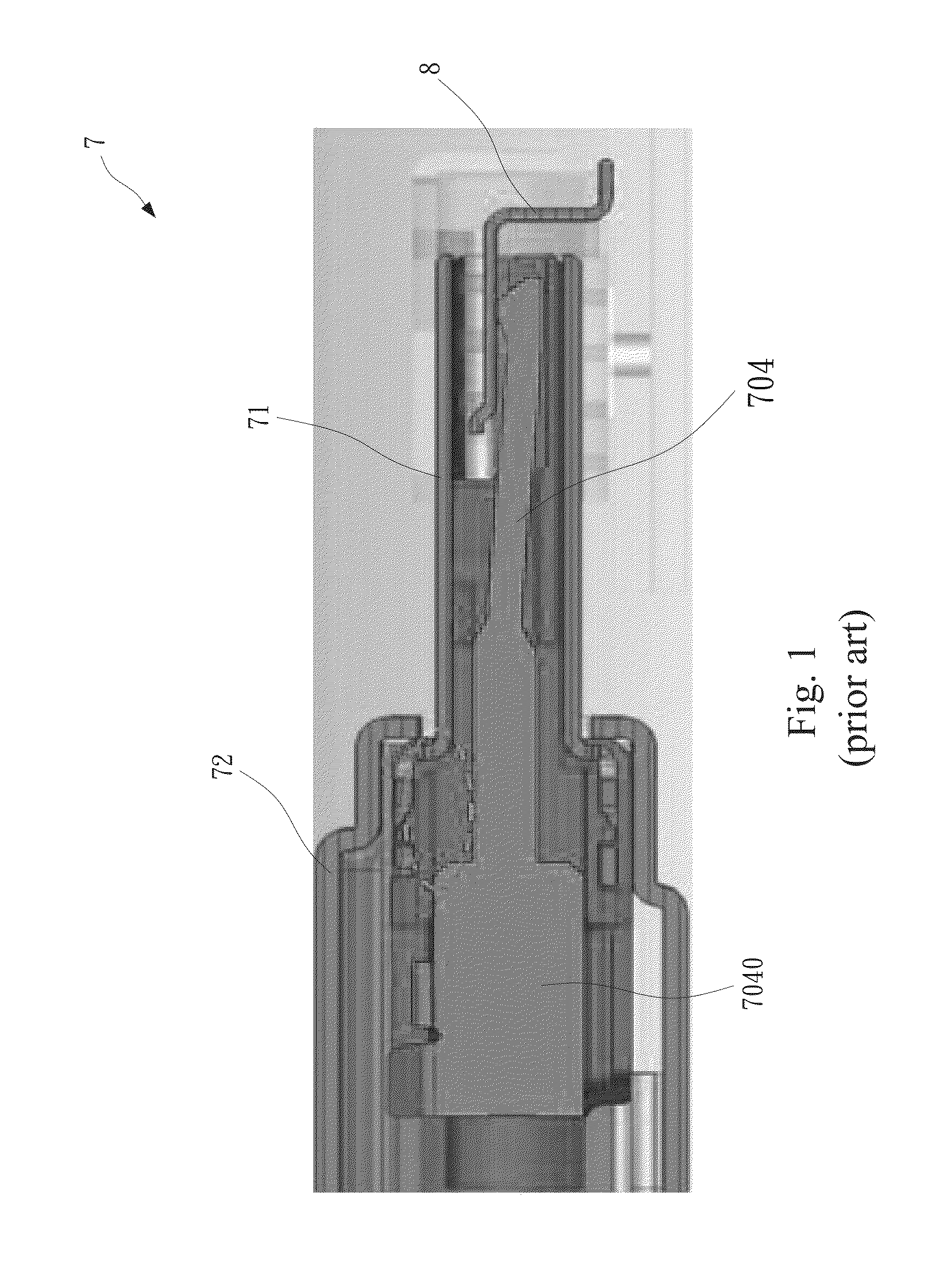
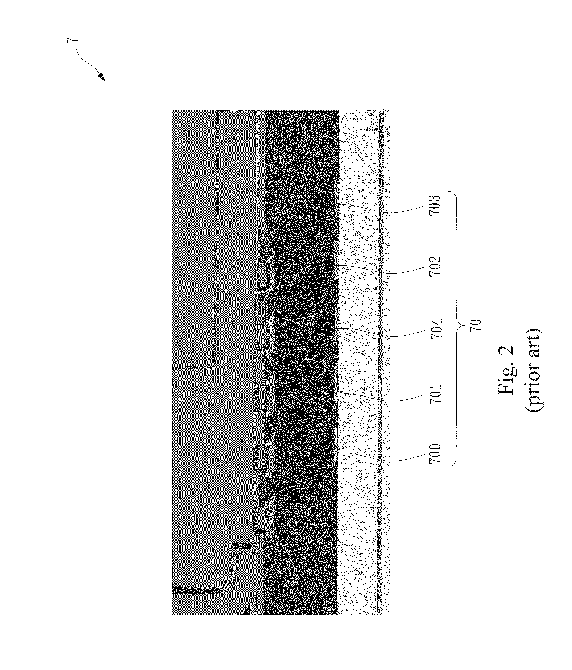
Because the USB 3.0 has extremely high transmission speed, problems that never took place before happened.
However, in high speed digital circuitry, one of the reasons that will affect information accuracy is the near end crosstalk.
Near end crosstalk is the electromagnetic coupling interference between two adjacent wires and delays the information reception to each wire, especially when the transmission directions of these two adjacent wires are the same.
The standard for crosstalk is about 1.2% and the method discussed above reaches only about 0.7% to 1%, which still causes serious crosstalk interference, delays signal transmission and ultimately reduces information accuracy for the USB 3.0.

Method used


Image

  • Connector with low near end crosstalk
  • Connector with low near end crosstalk
  • Connector with low near end crosstalk

Examples


Embodiment Construction

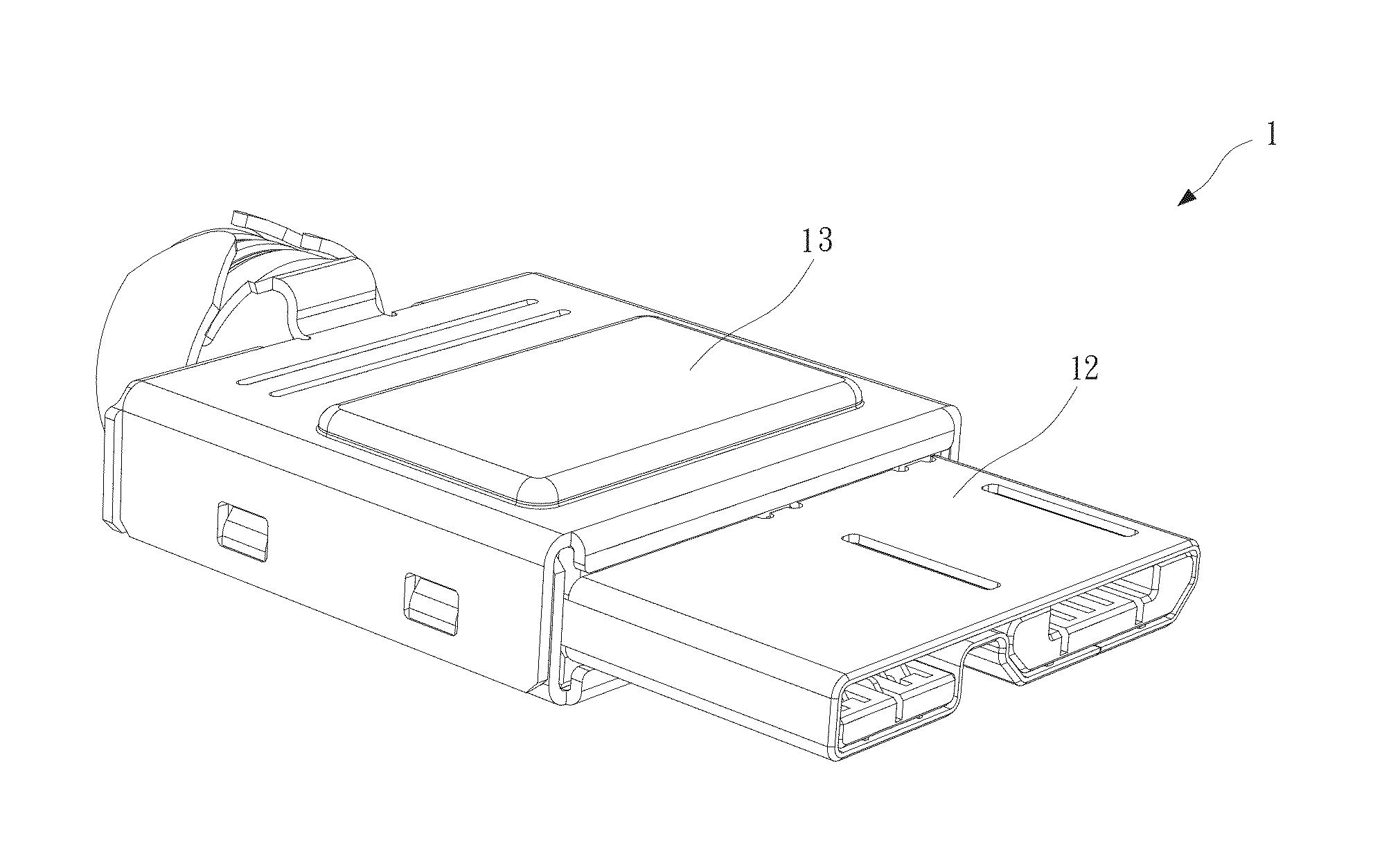
[0024]With reference to FIGS. 3 to 7B, the connector constructed in accordance with the preferred embodiment of the present invention is composed of a fixture 10 with multiple slits 100 defined therein, terminals 11, a metal housing 12 and a metal casing 13.

[0025]One ends of the multiple terminals 11 are received in corresponding slits 100 and the other ends thereof are exposed from the fixture 10. The terminals 11 are composed of first top signal terminals 110, first bottom signal terminals 111, second top signal terminals 112, second bottom signal terminals 113 and a ground terminal 114. One end of the ground terminal 114 is provided with a metallic baffle 1140 with one side of which corresponds to the first top signal terminals 110 and the first bottom signal terminals 111 and the other side of which corresponds to the second top signal terminals 112 and the second bottom signal terminals 113.

[0026]The metal housing 12 encloses the exposed other ends of the terminals 11 and is co...


PUM


Abstract

A connector has a fixture with multiple slits defined therein, multiple terminals, a metal housing and a metal casing. One ends of the terminals are received in corresponding slits and the other ends of the terminals are exposed from the fixture. The metal housing encloses the exposed other ends of the terminals and connected to the metallic baffle. The metal casing encloses the fixture and a part of the metal housing.

Description

CROSS-REFERENCE TO RELATED APPLICATION[0001]This application claims priority from application No. 201220303832.7, filed on Jun. 27, 2012 in the State Intellectual Property Office of The People's Republic of China.FIELD OF THE INVENTION[0002]The invention relates to a connector and, more particularly, to a connector having a ground terminal provided with a metal baffle to separate groups of terminals and a hook integrally formed on the metal baffle to engage with the metal housing.BACKGROUND OF THE INVENTION[0003]USB (Universal Serial Bus) is a standard serial bus for connecting a computer to a foreign device and also an input / output interface protocol, which is widely used in information products such as personal computers, mobile communication devices and can also be expanded to cameras, digital TVs, video game machines . . . etc.[0004]Following the demands for transmission speed and storing capacity, the transmission speed for USB is up grated from the initial USB 1.0 (Max transmi...

Claims


Application Information

Patent Timeline
Patent Type & Authority Applications(United States)
IPC IPC(8): H01R24/28
CPCH01R13/6471
Inventor CHU, PING-CHUANZHANG, SHUN-HUAZHU, ZHONG-WUZHANG, XIANG-WEI
Owner ADVANCED CONNECTEK INC
Learn More