Aerodynamic seals for rotary machine

a technology of aerodynamic seals and rotary machines, applied in the direction of engine seals, non-positive displacement fluid engines, pump components, etc., can solve the problems of poor efficiency of turbo-machineries, affecting efficiency, and leaked fluids failing to perform useful work

Active Publication Date: 2014-01-09
GENERAL ELECTRIC CO
View PDF6 Cites 56 Cited by
  • Summary
  • Abstract
  • Description
  • Claims
  • Application Information

AI Technical Summary

Benefits of technology

[0006]In accordance with an embodiment of the invention, an aerodynamic seal assembly for a rotary machine is provided. The assembly includes multiple sealing device segments disposed circumferentially intermediate to a stationary housing and a rotor. Each of the segments includes a shoe plate with a forward-shoe section and an aft-shoe section having multiple labyrinth teeth therebetween facing the rotor. The shoe plate is configured to allow a high pressure fluid to a front portion of the plurality of the labyrinth teeth and a low pressure fluid behind the plurality of the labyrinth teeth and further configured to generate an aerodynamic force between the shoe plate and the rotor. The sealing device segment also includes multiple bellow springs or flexures connected to the shoe plate and to a top interface element, wherein the multiple bellow springs or flexures are configured to allow the high pressure fluid to occupy a forward cavity and the low pressure fluid to occupy an aft cavity. Further, the sealing device segments include a secondary seal attached to the top interface element at one first end and positioned about the multiple bellow springs or flexures and the shoe plate at one second end.
[0007]In accordance with an embodiment of the invention, an aerodynamic sealing device for turbine components is provided. The sealing device includes a shoe plate having multiple labyrinth teeth between a forward shoe plate section and an aft shoe plate section facing a rotatable element. The shoe plate is configured to allow a high pressure fluid to a front portion of the plurality of the labyrinth teeth and a low pressure fluid behind the plurality of the labyrinth teeth and further configured to generate an aerodynamic force between the shoe plate and the rotor. The sealing device also includes multiple bellow springs or flexures connected to the shoe plate and to a top interface element, wherein the plurality of bellow springs or flexures are configured to allow the high pressure fluid to occupy a forward cavity and the low pressure fluid to occupy an aft cavity. Further, the sealing device includes a secondary seal connected to the top interface element at one first end and positioned about the plurality of bellow springs or flexures and the shoe plate at one second end, wherein the secondary seal disposed within the sealing device is configured to form the forward cavity and the aft cavity towards a high pressure side and a low pressure side of the rotary machine.

Problems solved by technology

Leakage of fluid through these gaps from regions of high pressure to regions of low pressure may result in poor efficiency for the turbo-machinery.
Such leakage may impact efficiency in that the leaked fluids fail to perform useful work.
The sealing systems, however, often are subject to relatively high temperatures, thermal gradients, and thermal and mechanical expansion and contraction during various operational stages that may increase or decrease the clearance therethrough.
For example, traditional labyrinth seals that are assembled to run very tight clearance during start-up transient phase might run with large clearances during steady state operations, thereby leading to poor performance at steady state operation.

Method used


Image

  • Aerodynamic seals for rotary machine
  • Aerodynamic seals for rotary machine
  • Aerodynamic seals for rotary machine

Examples


Embodiment Construction

[0021]When introducing elements of various embodiments of the present invention, the articles “a,”“an,”“the,” and “said” are intended to mean that there are one or more of the elements. The terms “comprising,”“including,” and “having” are intended to be inclusive and mean that there may be additional elements other than the listed elements. Any examples of operating parameters are not exclusive of other parameters of the disclosed embodiments.

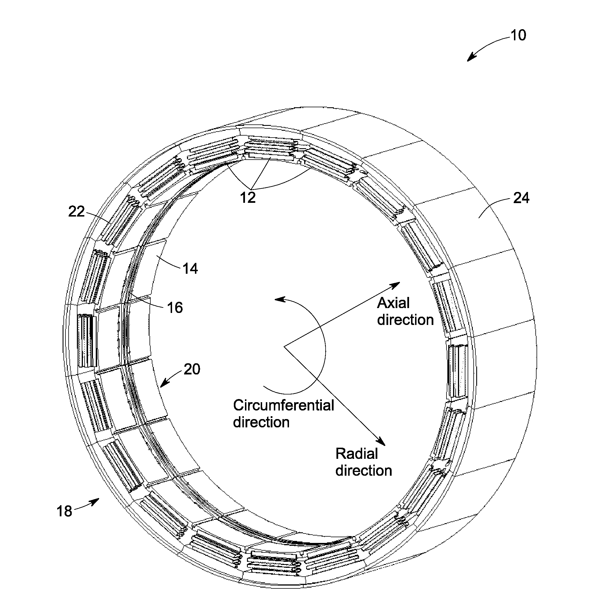
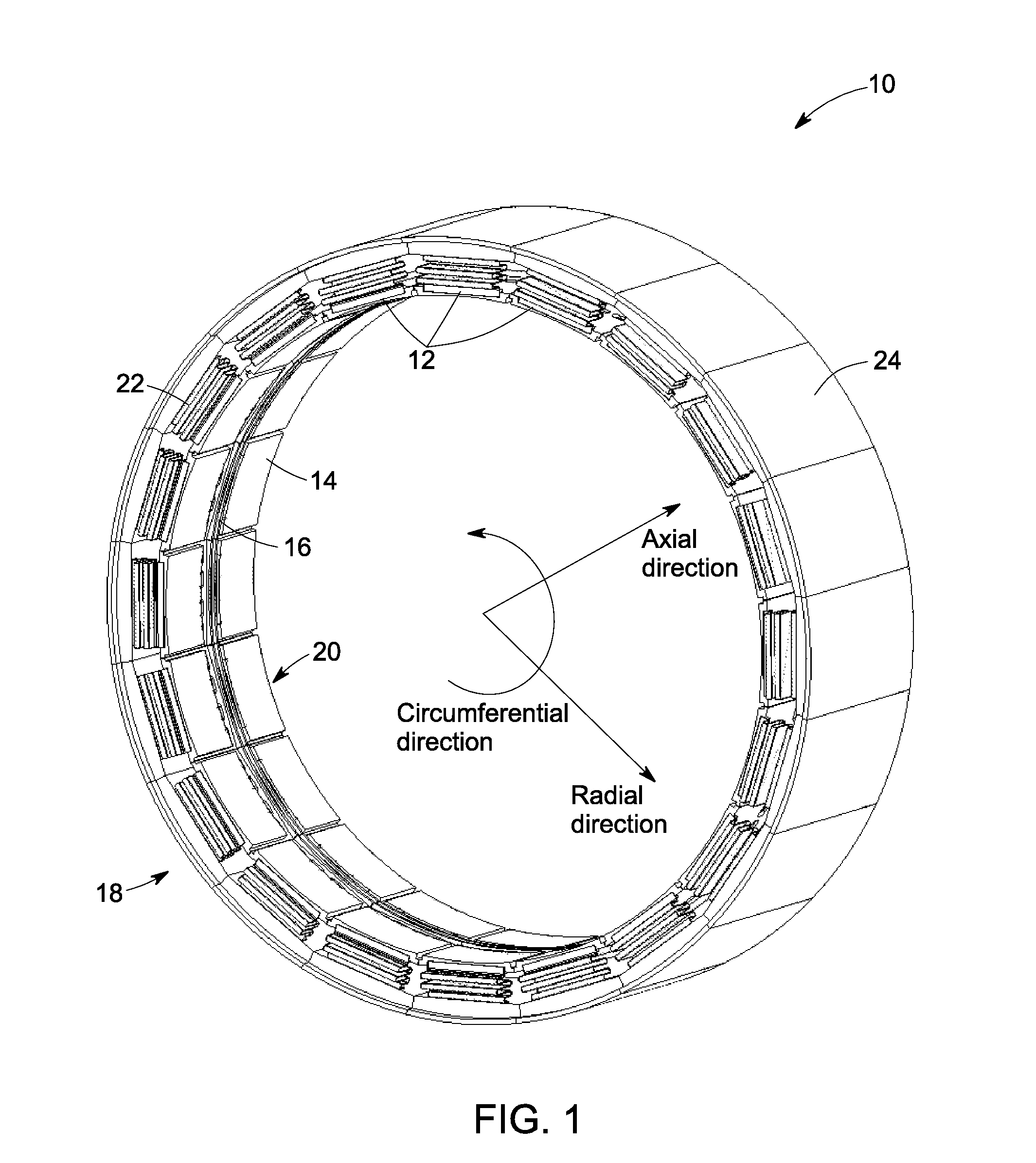
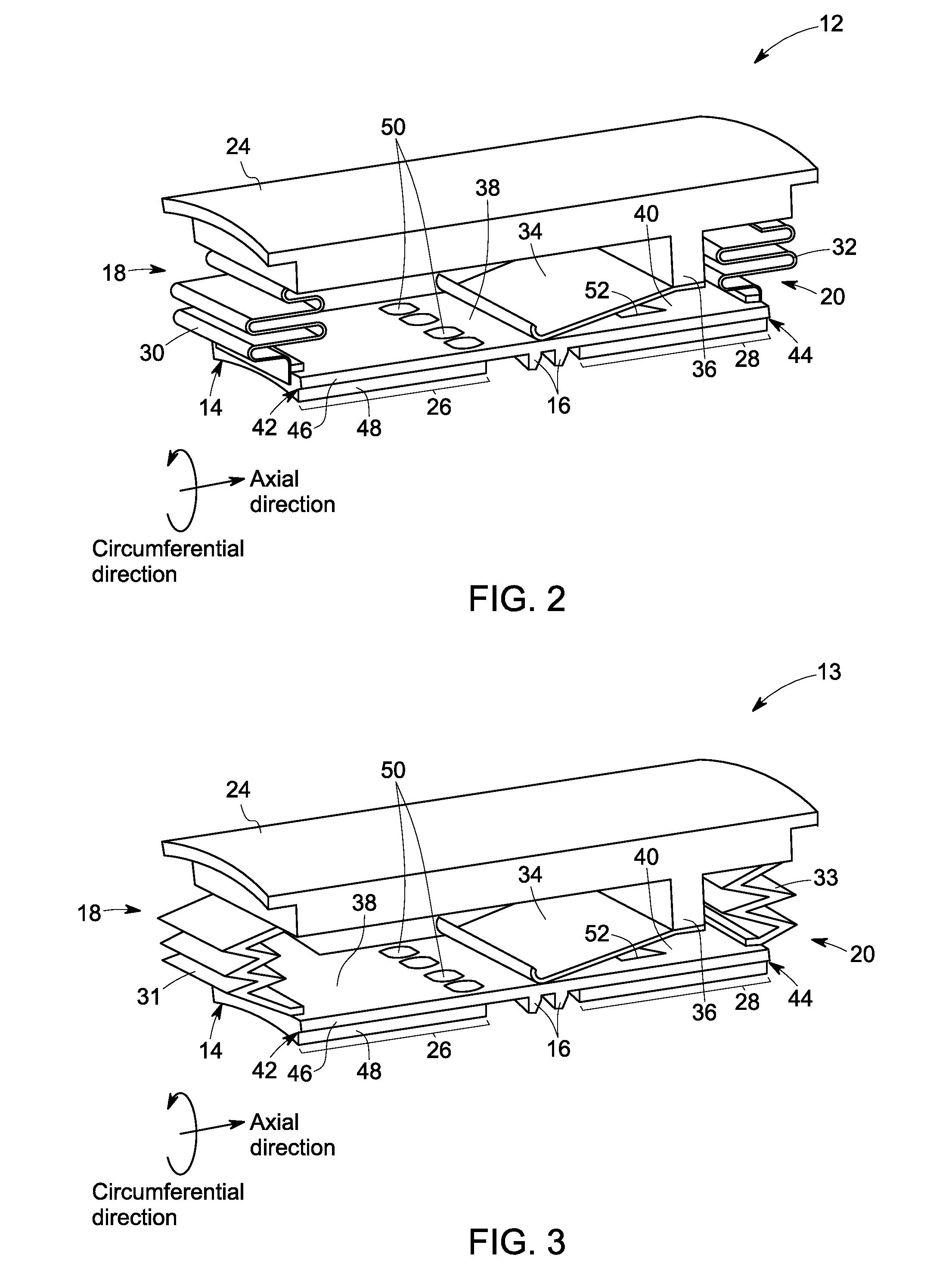
[0022]FIG. 1 is a perspective view of an aerodynamic seal assembly 10 for a rotary machine in accordance with an embodiment of the present invention. The aerodynamic seal assembly 10 is circumferentially arranged around a rotor shaft (not shown) such that the seal assembly 10 is intermediate to a stationary housing (not shown) and the rotor shaft. The seal assembly 10 includes multiple sealing device segments 12 located adjacent to each other to form the seal assembly 10. Each of the sealing device segment 12 includes a shoe plate 14 located pr...


PUM


Abstract

An aerodynamic seal assembly for a rotary machine is provided. The assembly includes multiple sealing device segments disposed circumferentially intermediate to a stationary housing and a rotor. Each of the segments includes a shoe plate with a forward-shoe section and an aft-shoe section having multiple labyrinth teeth therebetween facing the rotor. The shoe plate is configured to allow a high pressure fluid to a front portion of the plurality of the labyrinth teeth and a low pressure fluid behind the plurality of the labyrinth teeth and further configured to generate an aerodynamic force between the shoe plate and the rotor. The sealing device segment also includes multiple bellow springs or flexures connected to the shoe plate and to a top interface element, wherein the multiple bellow springs or flexures are configured to allow the high pressure fluid to occupy a forward cavity and the low pressure fluid to occupy an aft cavity. Further, the sealing device segments include a secondary seal attached to the top interface element at one first end and positioned about the multiple bellow springs or flexures and the shoe plate at one second end.

Description

STATEMENT REGARDING FEDERALLY SPONSORED RESEARCH & DEVELOPMENT[0001]This invention was made with partial Government support under contract number DE-FC26-05NT42643 awarded by U.S. Department of Energy. The Government has certain rights in the invention.BACKGROUND[0002]The present application relates generally to seal assemblies for turbo-machinery and more particularly relates to advanced aerodynamic seal assemblies for sealing rotor / stator gaps and the like.[0003]Various types of turbo-machinery, such as gas turbine engines, aircraft engines and steam turbines, are known and widely used for power generation, propulsion, and the like. The efficiency of the turbo-machinery depends in part upon the clearances between the internal components and the leakage of primary and secondary fluids through these clearances. For example, large clearances may be intentionally allowed at certain rotor-stator interfaces to accommodate large, thermally or mechanically-induced, relative motions. Leaka...

Claims


Application Information

Patent Timeline
Patent Type & Authority Applications(United States)
IPC IPC(8): F16J15/447
CPCF16J15/447F01D11/025F01D11/04F01D11/14F16J15/442F16J15/445F04D29/164F04D29/526
Inventor BIDKAR, RAHUL ANILCIRRI, MASSIMILIANOTHATTE, AZAM MIHIRWILLIAMS, JOHN ROBERT
Owner GENERAL ELECTRIC CO
Why Eureka
Try Eureka