Shade with a Shear Pin and Method for Pretensioning a Shade

a technology of roller shades and shear pins, applied in the field of roller shades, can solve the problem that the ability of the average user of roller shades to pretension the counterbalancing mechanism is not enough, and achieve the effect of improving the ability of the average user of the roller shad

Inactive Publication Date: 2014-01-16
HOMERUN HLDG
View PDF0 Cites 34 Cited by
  • Summary
  • Abstract
  • Description
  • Claims
  • Application Information

AI Technical Summary

Benefits of technology

[0010]In accordance with yet another embodiment of the present invention, a roller shade may be provided. The roller shade may include: means for rolling; means for rotatabling supporting the means for rolling; means for counterbalancing configured to counter balance a rotation of the means for rolling wherein the means for counterbalancing is configured to impart a rotational force on the means for roll and the rotational force is adjusted by rotating the mean for rotatabling supporting the means for rolling; and means for locking attached to the means for rolling and configured to lock the means for rotatabling supporting the means for rolling at a given angular orientation, wherein the means for locking includes a means for fusing.

Problems solved by technology

Pretensioning the counterbalancing mechanism may be above the ability of the average user of a roller shade.

Method used


Image

  • Shade with a Shear Pin and Method for Pretensioning a Shade
  • Shade with a Shear Pin and Method for Pretensioning a Shade
  • Shade with a Shear Pin and Method for Pretensioning a Shade

Examples


Embodiment Construction

[0019]The invention will now be described with reference to the drawing figures, in which like reference numerals refer to like parts throughout. An embodiment in accordance with the present invention provides a blind assembly that includes a counterbalancing mechanism that can be pretensioned to a desired level of tensioning.

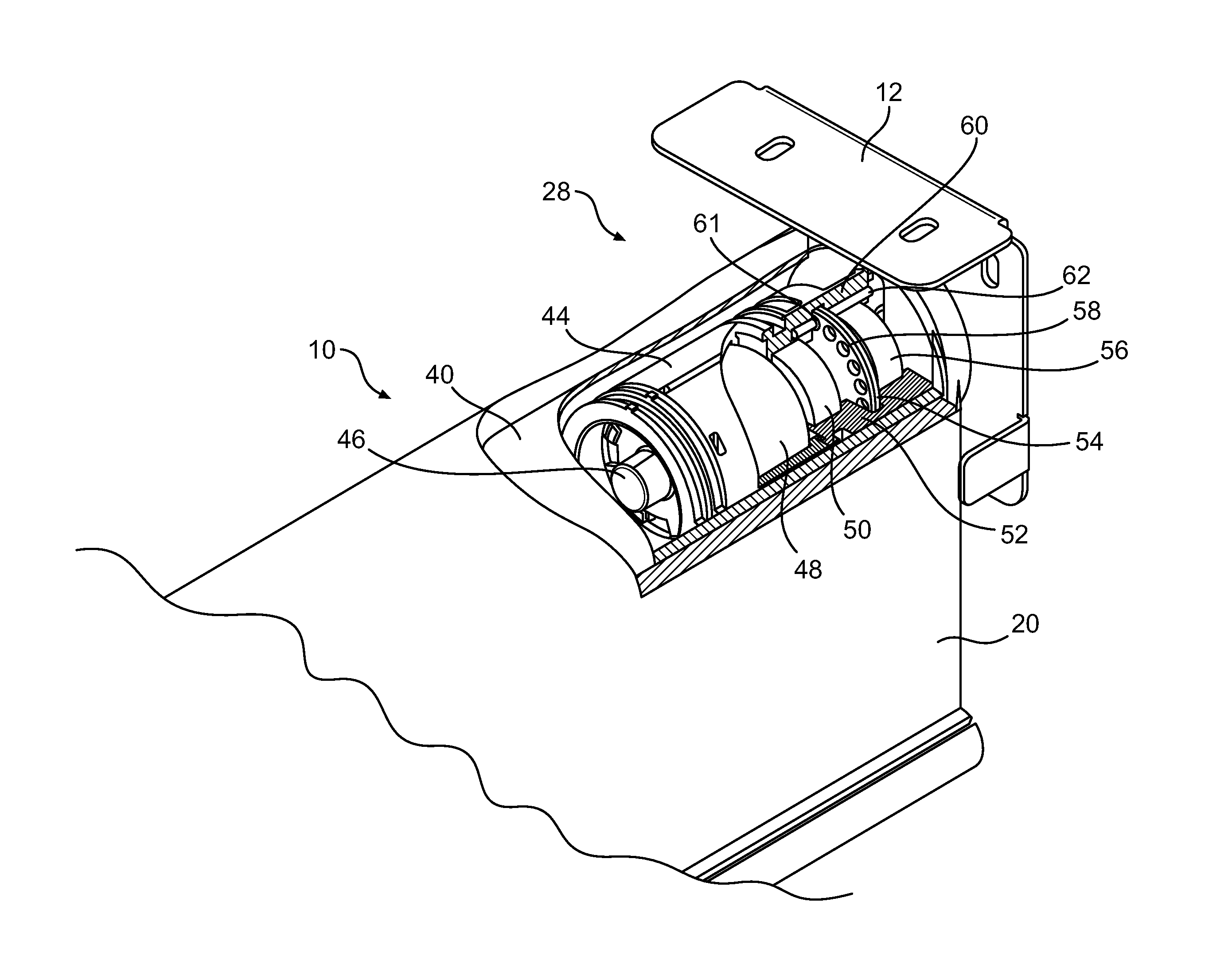
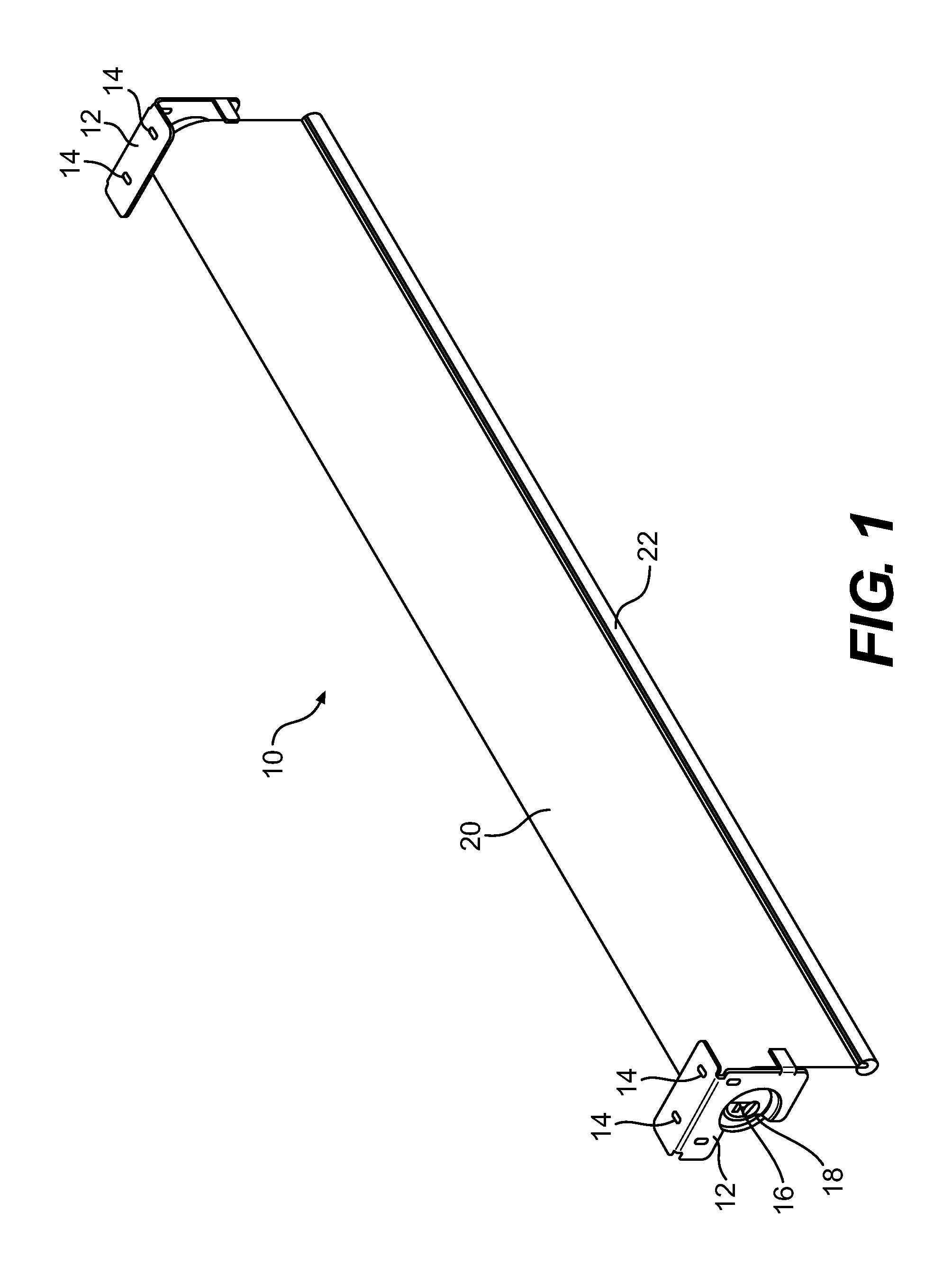
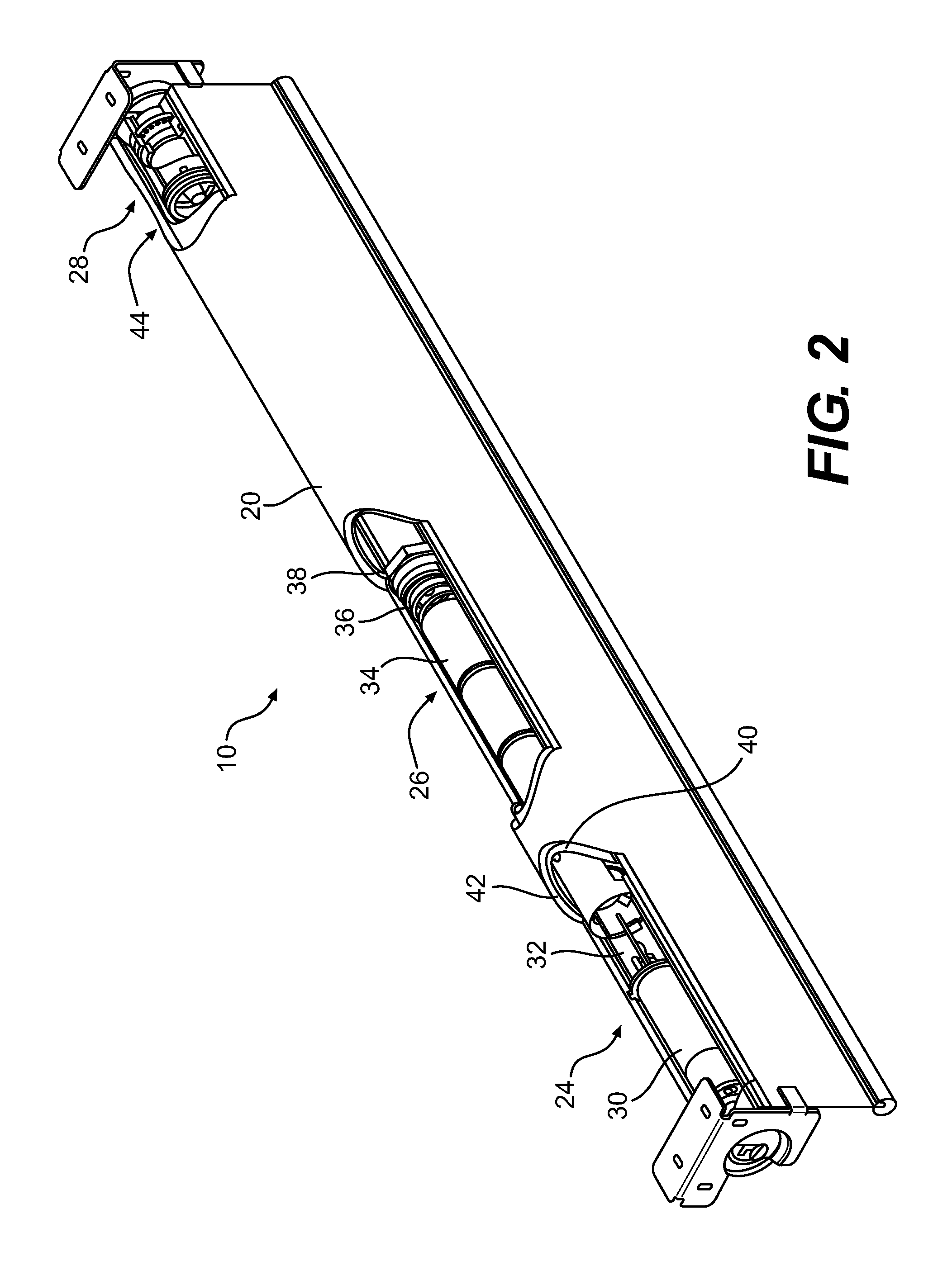
[0020]FIG. 1 illustrates a blind assembly 10 in accordance with an embodiment of the invention. The blind assembly 10 may be mounted upon brackets 12. The brackets 12 may be mounted to a window frame or a wall to place the blind assembly 10 in a desirable location within respect to a window. The brackets 12 may include mounting holes 14 which may be used to mount the brackets 12 via fasteners that may be inserted into the mounting holes 14. The brackets 12 may include a slot 16 which is dimensioned and configured to accept and support a shaft 18 of the blind assembly 10. The blind assembly 10 may include blind material 20. The blind material 20 may include a ra...


PUM

PropertyMeasurementUnit
rotational forceaaaaaaaaaa
tensionaaaaaaaaaa
diameteraaaaaaaaaa

Abstract

A roller shade is provided. The roller shade may include: a roller; an axle located in the roller; an adjustable counterbalancing mechanism configured to counter balance a rotation of the roller wherein the counterbalancing mechanism is configured to impart a rotational force on the roller and the rotational force is adjusted by rotating the axle; and a locking mechanism attached to the roller and configured to lock the axle at a given angular orientation, wherein the locking mechanism includes a shear pin. A method of tensioning a counterbalancing mechanism may also be provided. The method may include: mounting the counterbalancing mechanism to a shaft; mounting the lock wheel to the shaft; turning the shaft to tension the counterbalancing mechanism; and inserting a shear pin into a hole in the lock wheel to lock the shaft in place.

Description

FIELD OF THE INVENTION[0001]The present invention relates generally to a roller shade used to as a window covering. More particularly, the present invention relates to a mechanism for providing a spring biased counterbalance for the roller shade.BACKGROUND OF THE INVENTION[0002]Roller shades are used to provide a window covering that selectively allows privacy and / or limits light coming through a window. As windows are sometimes desired to be covered and uncovered, shades may be moved from a covering position to an unobstructed position by rolling the roller shade to a raised position.[0003]The roller shades may be manually operated by a user or in other instances may be operated by an electric motor. In order to reduce the amount of effort that a user or a motor must exert to operate the roller shade, a spring counterbalancing system may be used to mitigate the effects of the weight of the shade when moving the roller shade up or down.[0004]In order for the counterbalancing mechani...

Claims


Application Information

Patent Timeline
Patent Type & Authority Applications(United States)
IPC IPC(8): E06B9/62B23P11/00E06B9/72E06B9/44E06B9/68
CPCE06B9/42E06B9/56E06B9/60E06B2009/801Y10T29/49826
Inventor MULLET, WILLIS JAYBRUNK, DARRIN W.
Owner HOMERUN HLDG
Why Eureka
Try Eureka