Variable angle bone fixation device

a bone fixation device and variable angle technology, applied in the field of variable angle bone fixation device, can solve the problems of bone fixation procedure to lose efficacy, loss of bone fixation strength,

Active Publication Date: 2014-01-16
DEPUY SYNTHES PROD INC
View PDF7 Cites 99 Cited by
  • Summary
  • Abstract
  • Description
  • Claims
  • Application Information

AI Technical Summary

Problems solved by technology

However, the engagement threads of the head of such variable angle screw heads with the threading of the plate hole may burr threads of one or both of the bone screw and the bone plate, causing a loss in bone fixation strength.
Damage to the bone plate or bone screw in this manner may cause the bone fixation procedure to lose efficacy.

Method used


Image

  • Variable angle bone fixation device
  • Variable angle bone fixation device
  • Variable angle bone fixation device

Examples


Embodiment Construction

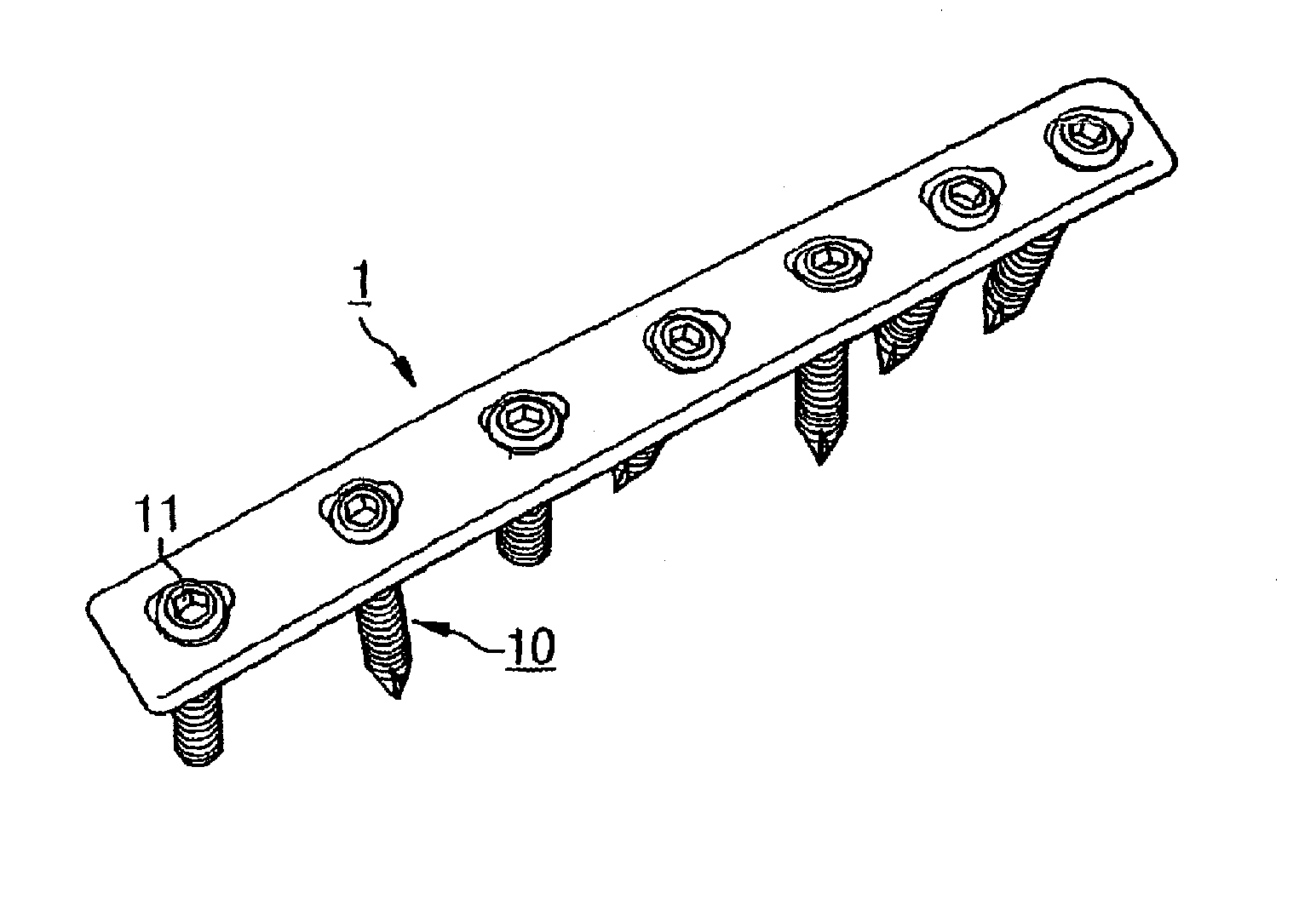
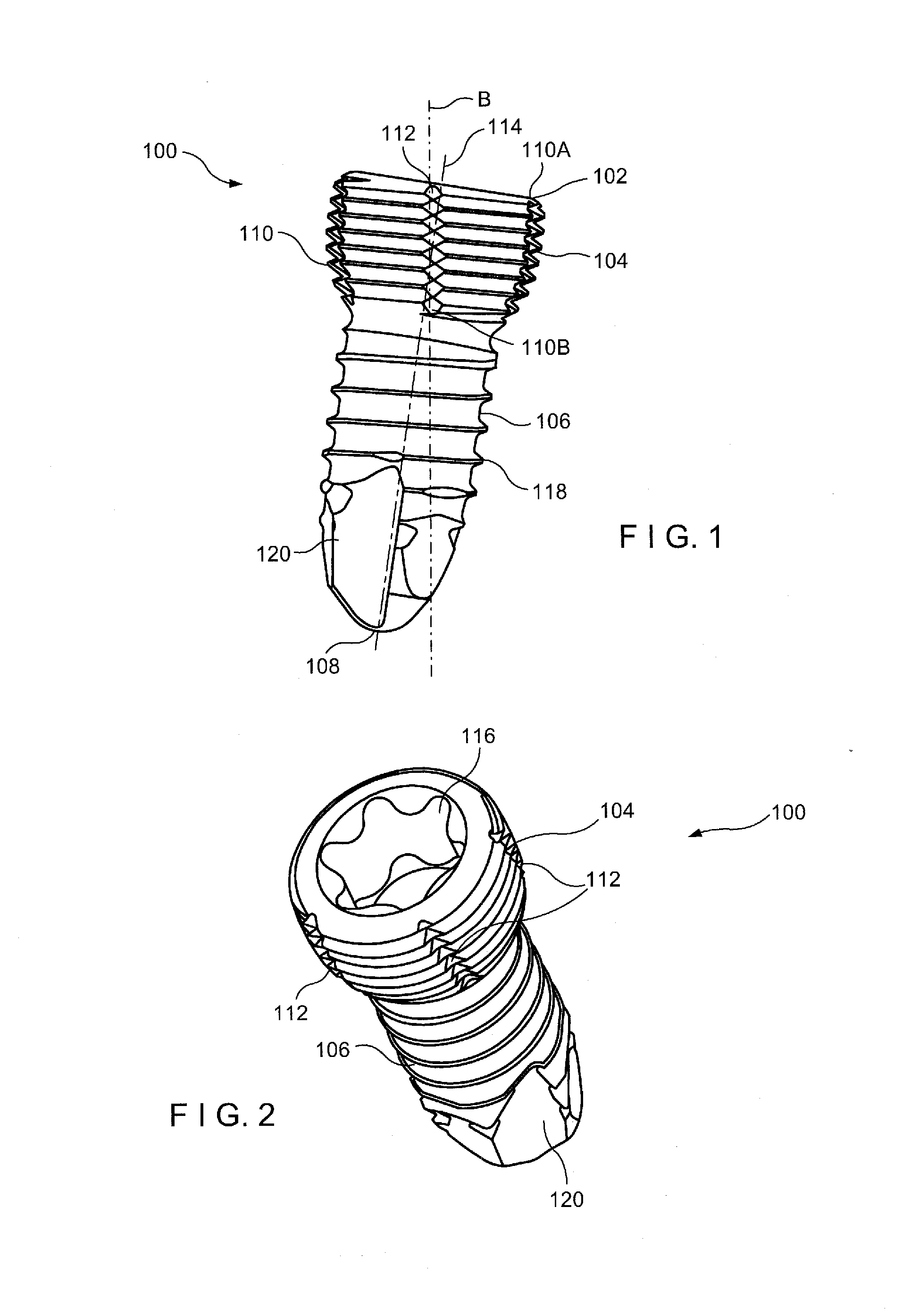
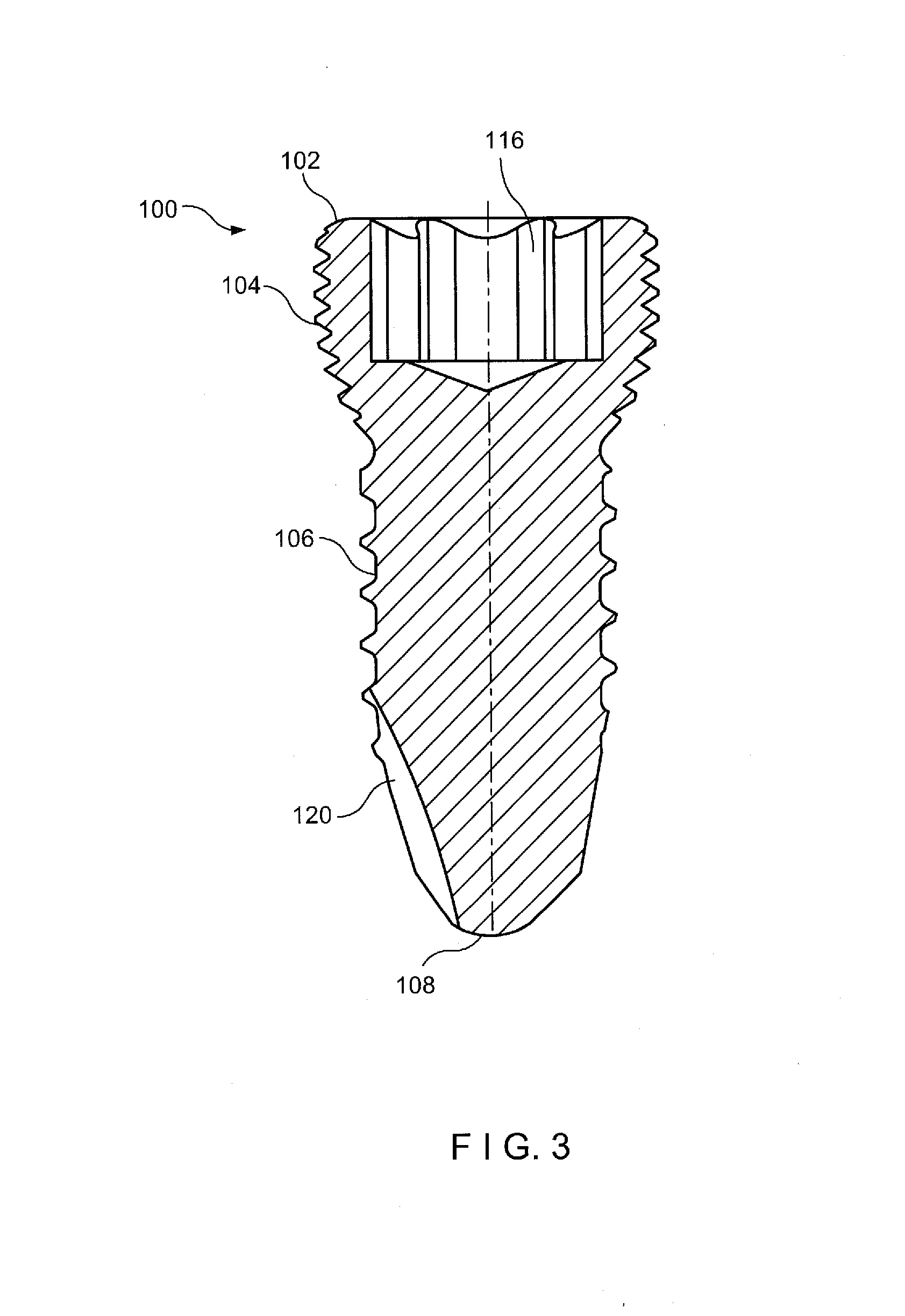
[0064]The present invention may be further understood with reference to the following description and the appended drawings, wherein like elements are referred to with the same reference numerals. The present invention relates to the stabilization of bones and, in particular, to the stabilization of a fractured or otherwise damaged bone using a bone screw inserted through a bone fixation device (e.g., a bone plate). Exemplary embodiments of the present invention describe a variable angle bone screw having a threaded head and a threaded shaft and having a carburized or nitrided outer surface configured to increase a surface hardness thereof to a desired level. The threaded head comprises one or more grooves extending into an outer surface thereof at an angle relative to a longitudinal axis of the bone screw to aid in alignment of the threads of the head with threads of a variable angle screw hole of the bone fixation device. The shaft comprises one or more notches extending into an o...


PUM


Abstract

A bone fixation element includes a threaded head and a shaft extending along a longitudinal axis from a proximal end to a distal end, an outer surface of the head being one of carburized and nitrided and including a first groove extending into an outer surface of the head along a path interrupting the threading and extending along an angle counter to an angle of the threading.

Description

PRIORITY CLAIM[0001]This application is a Continuation-In-Part of U.S. patent application Ser. No. 13 / 534,831 filed on Jun. 27, 2012 and entitled “Variable Angle Bone Fixation Device” which is expressly incorporated herein, in their entirety, by reference.BACKGROUND[0002]Bone fixation plates are often positioned over a fractured or otherwise damaged portion of bone and secured thereto using bone screws inserted through screw holes of the bone fixation plate. The screw holes extend transversely through the bone plate and are sometimes formed with threads to lockingly engage a threaded head of the bone screw. Variable angle screws are often employed which permit a user to insert the screw through the plate at a user-selected angle relative to an axis of the plate hole. However, the engagement threads of the head of such variable angle screw heads with the threading of the plate hole may burr threads of one or both of the bone screw and the bone plate, causing a loss in bone fixation s...

Claims


Application Information

Patent Timeline
Patent Type & Authority Applications(United States)
IPC IPC(8): A61B17/80A61B17/88
CPCA61B17/8057A61B17/88A61B17/56A61B17/8052A61B17/8061A61B17/84A61B17/86A61B17/8605A61B17/866A61B2017/8655
Inventor KOAY, KENNYMCMILLAN, RODKOBAYASHI, KENNETHHAAG, RENELIMOUZE, ROBERTWAHL, MIKEROCCI, MIRKO
Owner DEPUY SYNTHES PROD INC
Why Eureka
Try Eureka