
Shaft and bearing arrangement and hydrostatic spindle for high speed applications

Inactive Publication Date: 2014-01-30
KASHCHENEVSKY LEONID +1
View PDF7 Cites 5 Cited by
  • Summary
  • Abstract
  • Description
  • Claims
  • Application Information

AI Technical Summary

Benefits of technology

The spindle described in this patent has two bearing arrangements: a radial hydrostatic bearing and a thrust hydrostatic bearing. The first bearing arrangement has a pocket and a recess between it and the shaft, while the second arrangement has a chamber between it and the shaft. The two arrangements form an opposing force on the shaft. The shaft and bearing arrangement also has two rings that support the shaft in different directions. The technical effect of this design is improved stability and reduced vIB of the spindle, which is beneficial for many applications such as machining and manufacturing.

Problems solved by technology

Heat generated by rotors is of primary concern since it can cause parts such as shafts to thermally expand in relation to bearings which can ultimately cause failure of bearing in a spindle.
There are, however, some issues that significantly restrict use of hydrostatic spindles in applications with high rotational speeds.
One such issue is shear friction in the bearings.
However, while lowering oil viscosity reduces the laminar component of the friction power it actually results in an increase in the turbulent component.
Additionally, oil flow rates that are too great will result in oil leakage.

Method used


Image

  • Shaft and bearing arrangement and hydrostatic spindle for high speed applications
  • Shaft and bearing arrangement and hydrostatic spindle for high speed applications
  • Shaft and bearing arrangement and hydrostatic spindle for high speed applications

Examples


Embodiment Construction

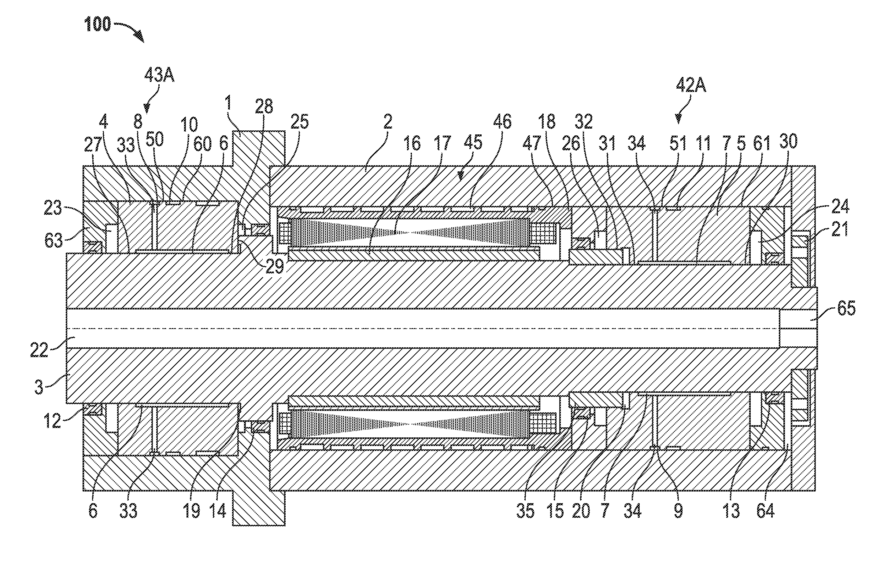
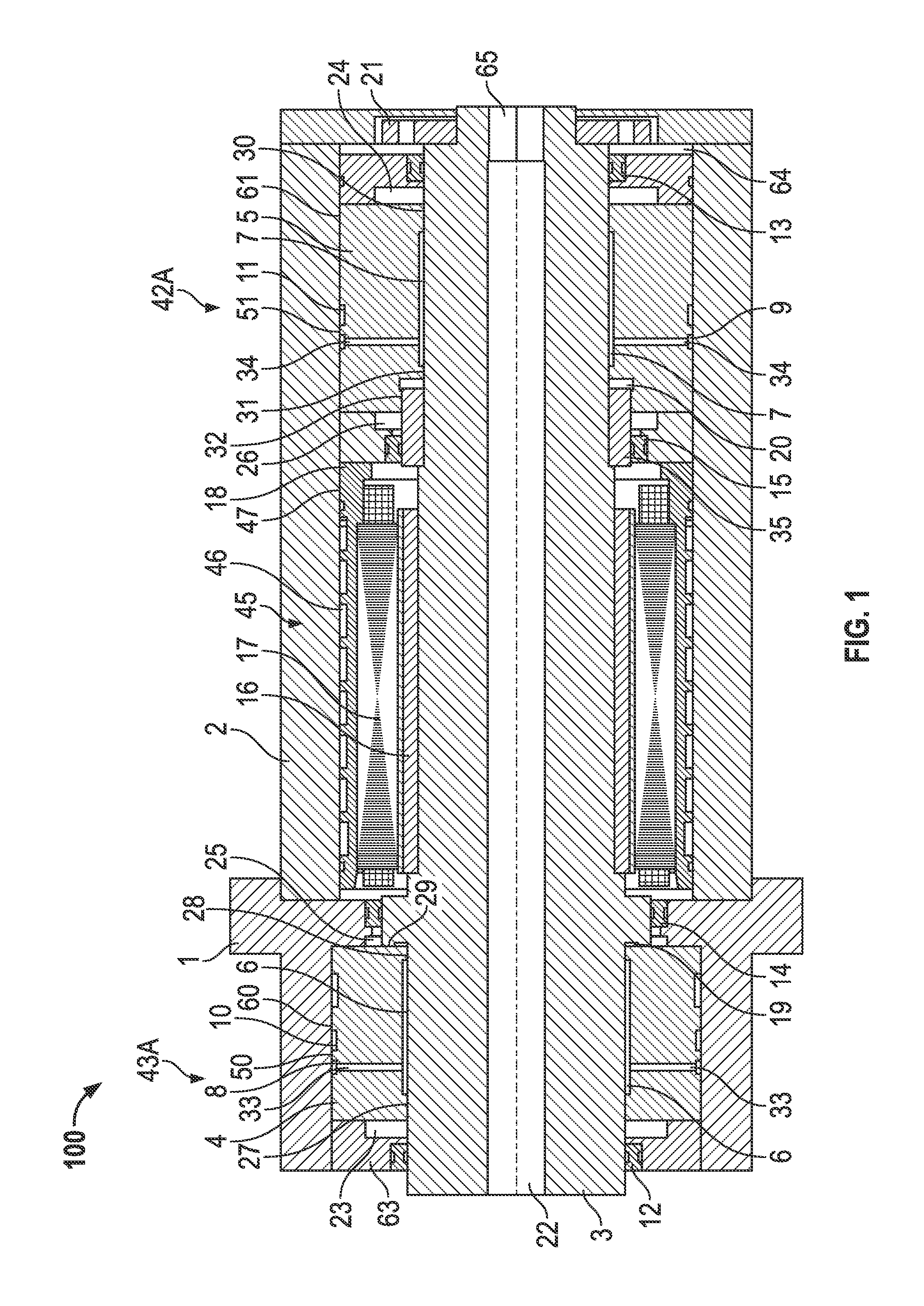
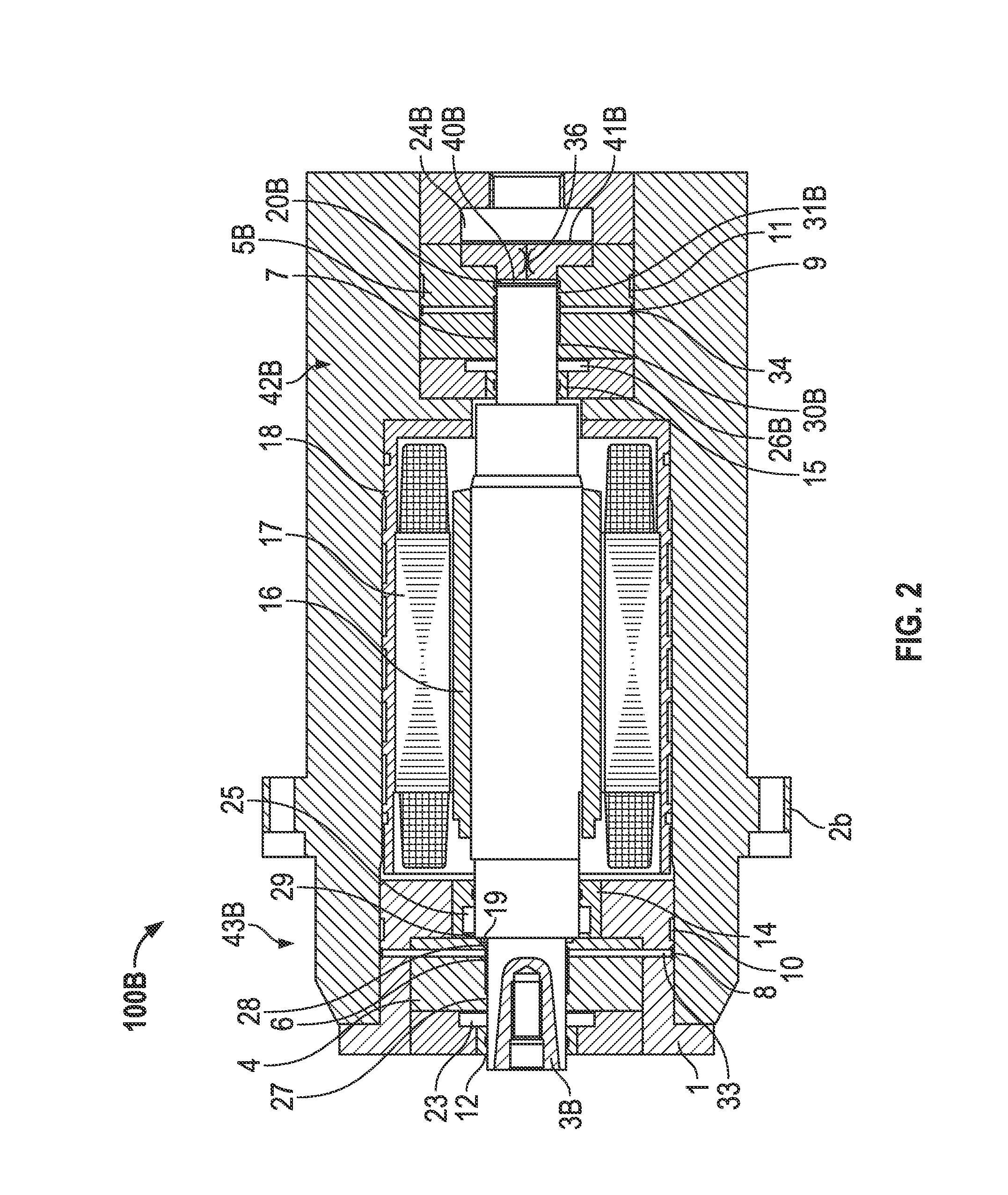
[0016]A detailed description of one or more embodiments of the disclosed apparatus and method are presented herein by way of exemplification and not limitation with reference to the Figure.

[0017]With hydrostatic bearings, friction power is extremely sensitive to the sizes of the bearing. Friction power is proportional to a cube of the bearing diameter in laminar flows, and grows at an even faster rate for turbulent flows. Since the instant invention is directed to spindles with high rotational speeds, small spindle shaft diameters are employed. Also, a reduction in a diameter of a journal bearing will nearly proportionally reduce the hydrostatic support stiffness. Additionally, since shaft bending stiffness is proportional to a fourth power of the shaft diameter it is reduced even more. Reliability issues and the ability of hydrostatic spindles to withstand overloading conditions are more critical for applications with high rotational speeds than it is for applications with low and ...


PUM


Abstract

A spindle includes a housing, a shaft rotatably mounted to the housing, a first bearing arrangement and a second bearing arrangement. The first bearing arrangement has at least one first pocket defined between the first bearing arrangement and the shaft forming a first radial hydrostatic bearing and a longitudinal recess between the first bearing arrangement and the shaft forming a first portion of a thrust hydrostatic bearing. Fluid supplied to the first portion of the thrust hydrostatic bearing is supplied thereto from the at least one first pocket directly through a first radial gap defined between the first bearing arrangement and the shaft. The second bearing arrangement has a longitudinal chamber between the second bearing arrangement and the shaft forming a second portion of the thrust hydrostatic bearing. Longitudinal forces on the shaft from the first portion of the thrust longitudinal bearing and the second portion of the thrust longitudinal bearing are in opposing directions.

Description

CROSS REFERENCE TO RELATED APPLICATION[0001]This application claims priority to U.S. provisional application, 61 / 584,525, filed Jan. 9, 2012, the entire contents of which are incorporated herein by reference.BACKGROUND[0002]Hydrostatic spindles are one of the most precise types of spindle. They uniquely combine ultra-high rotational accuracy, high static stiffness, extremely high vibration resistance, high thermal stability with virtually limitless lifespan.[0003]In comparison to spindles with ball bearings or roller bearings, hydrostatic spindles have 10 to 20 times greater rotational accuracy at low and medium speeds range, and 20 to 40 times greater rotational accuracy at high rotational speeds.[0004]Additionally, in comparison to spindles with air-static bearings, hydrostatic spindles have about the same rotational accuracy, while their vibration resistance, load capacity and thermal stability are significantly greater. The vibration resistance of hydrostatic spindles is greater...

Claims


Application Information

Patent Timeline
IPC IPC(8): F16C32/06
CPCF16C32/064F16C32/0659
Inventor KASHCHENEVSKY, LEONIDLYSOV, YURI
Owner KASHCHENEVSKY LEONID
Learn More