Method and system for creating frame of reference for cas with inertial sensors

Inactive Publication Date: 2014-01-30
ORTHOSOFT ULC
View PDF11 Cites 49 Cited by
  • Summary
  • Abstract
  • Description
  • Claims
  • Application Information

AI Technical Summary

Benefits of technology

[0005]It is therefore an aim of the present invention to provide a novel method and system fo

Problems solved by technology

A common trait of inertial sensors is that they often do not provide positional informa

Method used


Image

  • Method and system for creating frame of reference for cas with inertial sensors
  • Method and system for creating frame of reference for cas with inertial sensors
  • Method and system for creating frame of reference for cas with inertial sensors

Examples


Embodiment Construction

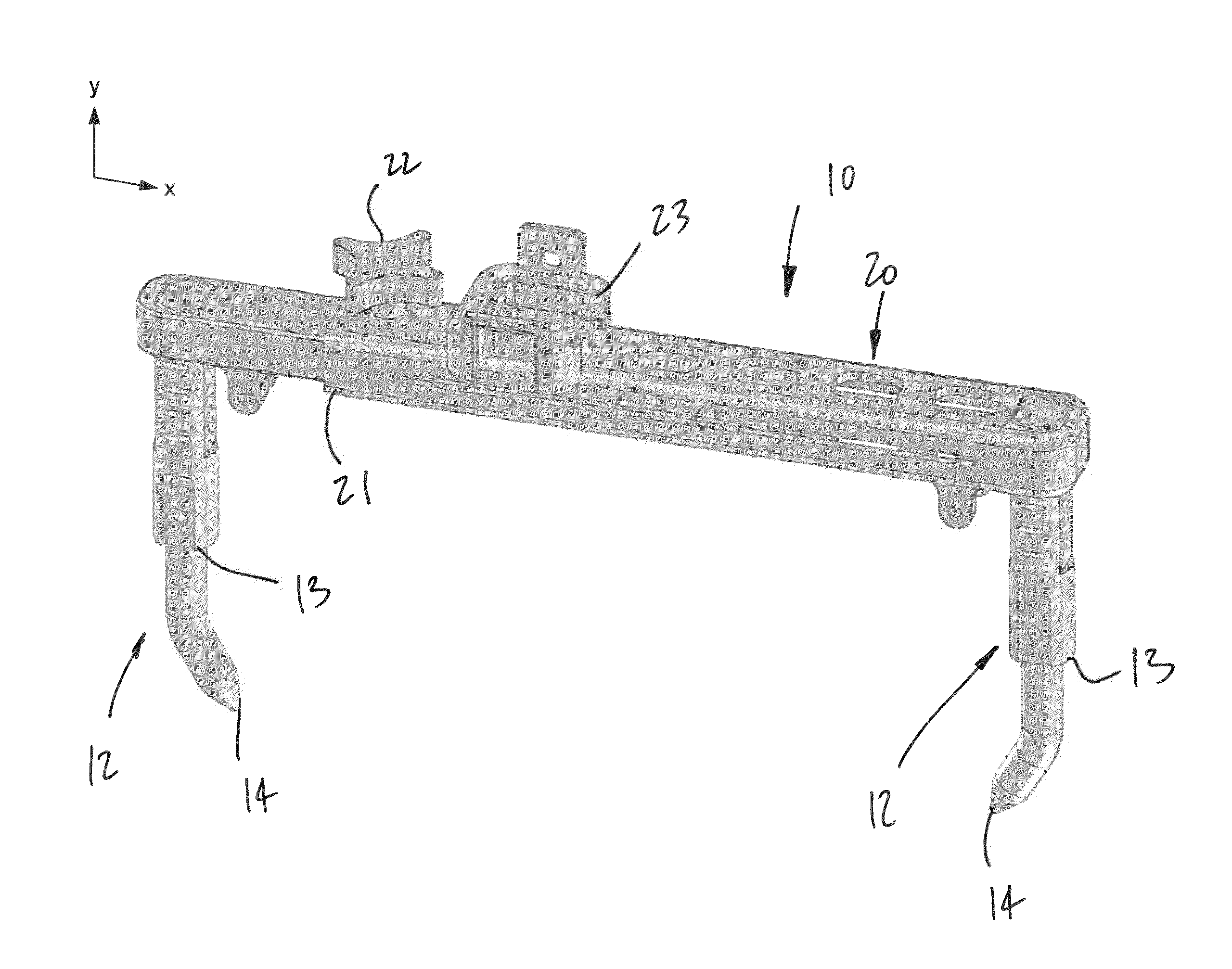
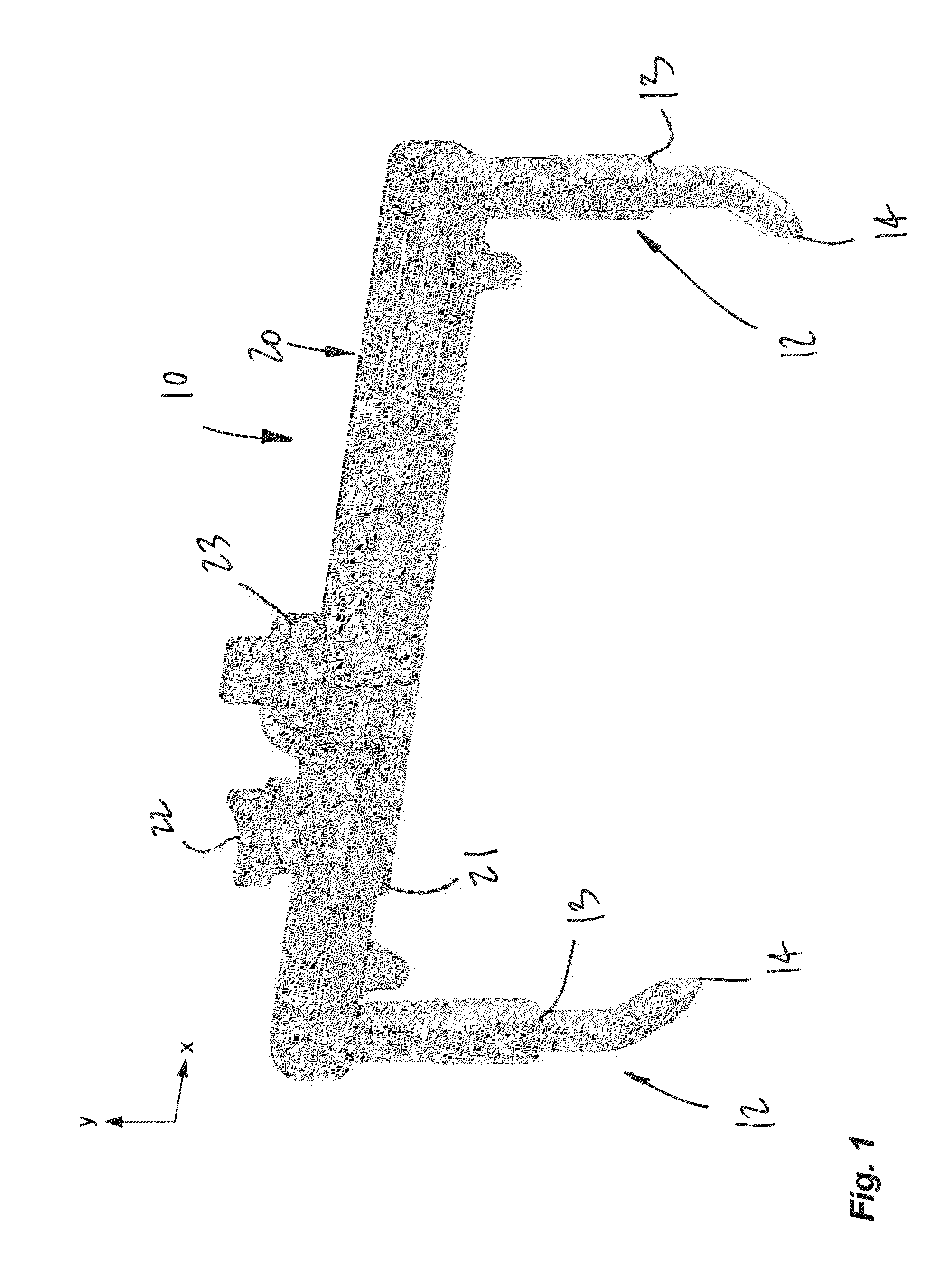
[0026]Referring to the drawings, and more particularly to FIG. 1, there is illustrated a caliper instrument 10 in accordance with the present application. The caliper instrument 10 may be used as part of a bone digitizer in a bone digitizing system, to create a frame of reference for subsequent navigation of tools relative to bones in surgery. The instrument 10 is referred to as a caliper, as it features a pair of legs 12 movable relative to one another, e.g., in a telescopic manner. The expression “caliper” is used nonrestrictively. Any other appropriate expression may be used to describe the instrument 10.

[0027]In the illustrated embodiment, the legs 12 of FIG. 1 each comprise a translational joint 13 so as to be expandable or contractible along the Y axis. For instance, the translational joints 13 may be any of sliding joint, telescopic joint, prismatic joint, indexing joint, etc. As an alternative, a single one of the legs may have a joint. It is also considered to use rotationa...


PUM


Abstract

A digitizer device comprises an elongated body and legs connected to the elongated body. At least one joint is between the legs and the elongated body such that free ends of the legs are displaceable relative to one another. An inertial sensor unit is connected to the elongated body, the inertial sensor unit having a preset orientation aligned with the elongated body. A table reference device comprises a body adapted to be fixed to an operating table. An inertial sensor unit is with a preset orientation related to the operating table. A patient coordinate system comprising orientation data obtained from the inertial sensor units of the digitizer device and the table reference device

Description

CROSS-REFERENCE TO RELATED APPLICATION(S)[0001]The present application claims priority on U.S. Patent Application No. 61 / 677,106, filed on Jul. 30, 2012, and incorporated herein by reference.FIELD OF THE APPLICATION[0002]The present application relates to computer-assisted surgery using inertial sensors, for instance orthopedic surgery.BACKGROUND OF THE ART[0003]Inertial sensors (e.g., accelerometers, gyroscopes, inclinometers, etc) are increasingly used in computer-assisted surgery for numerous reasons. Off-the-shelf inertial sensors are relatively inexpensive and produce results of sufficient precision and accuracy for orthopedic surgery applications.[0004]A common trait of inertial sensors is that they often do not provide positional information but, rather, simply orientational information, as they operate relative to gravity. Therefore, methods must be devised to create bone references and tools considering the absence of positional information.SUMMARY OF THE APPLICATION[0005]I...

Claims


Application Information

Patent Timeline
IPC IPC(8): A61B19/00
CPCA61B19/46A61B17/1742A61B2090/3983A61B2034/2048A61B2034/2068A61B34/20A61B90/06
Inventor PARADIS, FRANCOISZUHARS, JOELDUVAL, KARINECHEVRIER, MATHIEUAMIOT, LOUIS-PHILIPPEJANSEN, HERBERTVALIN, MYRIAMDYE, DONROBITAILLE, ISABELLEFERRON-FORGET, SIMONBAUDOIN, FRANCOIS
Owner ORTHOSOFT ULC
Why Eureka
Try Eureka